SignalFire DIN Gateway v2 Manuel utilisateur
Rev 1.0 SignalFire Telemetry
1
Interface Manual
DIN Gateway v2 - 485
SignalFire Part Numbers: GWDINv2-RS485
The SignalFire DIN Gateway V2 has the following features:
-RS485 connection to Modbus master device
-Wide range DC power input. 6 to 36VDC
-2 digital outputs (open collector), 2 digital inputs, and 3 analog inputs
-DIN rail mount
-Collects and caches Modbus data from all SignalFire remote nodes
-Provides configuration and status registers for remote configuration and status monitoring
-RP-SMA antenna port for connection to external 900MHz antenna
-Stores up to 4700 register values from any combination of remote nodes
-Supports transparent Modbus mode
-Internal Remote Shut Down (RSD) logic control option
-Slave register re-mapping
-Remote configuration of SignalFire devices
-Remote sensor configuration (PACTware and RadarMaster)
-Radio is FCC and IC approved
-AES 128bit Encryption
-Class 1 Division 2 Area certification pending

Rev 1.0 SignalFire Telemetry
2
Table of Contents
Specifications __________________________________________________________________________________________ 3
Connections and Components_________________________________________________________________________ 4
DIN Gateway V2 Connections __________________________________________________________________________________ 4
Status LEDs _____________________________________________________________________________________________________ 5
Operation______________________________________________________________________________________________ 5
Setup __________________________________________________________________________________________________ 5
Encryption ______________________________________________________________________________________________________ 7
Checking Remote Nodes ______________________________________________________________________________ 8
Remote Node Configuration ___________________________________________________________________________________ 9
Firmware Upgrades ___________________________________________________________________________________ 12
Rescue Gateway (ARM) Bootload _____________________________________________________________________________ 12
Remote Shutdown (RSD)______________________________________________________________________________ 13
Additional Options ____________________________________________________________________________________________ 18
Local Input/Output ___________________________________________________________________________________ 19
Analog/Relay Output Module _________________________________________________________________________________ 21
Slave Register Remapping ____________________________________________________________________________ 22
Fail Mode______________________________________________________________________________________________________ 24
Load/Save Files________________________________________________________________________________________________ 24
Gateway Event Log ___________________________________________________________________________________ 25
RS485 Details _________________________________________________________________________________________ 25
Network Map _________________________________________________________________________________________ 25
Modbus Gateway Register Map_______________________________________________________________________ 26
Gateway Configuration and Status Messages _________________________________________________________________ 26
Manual Revision History ______________________________________________________________________________ 29
Hazardous Location Certification _____________________________________________________________________ 30
Rev 1.0 SignalFire Telemetry
3
Specifications
Enclosure Size
5.00” tall × 4.04” wide × 1.63” deep
Weight
1.2 lbs. (0.54kg)
Power Source
6-36VDC external power source
Operating Current
25mA average current @ 12VDC
Analog Inputs (3)
0V –5V
Digital Inputs (2)
Dry contact or 30V max DC (push pull)
Digital Outputs (2)
Open collector, 1A, 30V max
Temperature Rating
-40°C to +85°C
Radio
902-928MHz ISM Band, FHSS radio, internal antenna
RP-SMA connector
Compliance
Certification pending for use in Class I, Division 2 groups C and D. EXi
[EXi] FCC/IC Certified.
The associated apparatus provides intrinsically safe outputs.
L’appareil associé fournit des sorties à sécurité intrinsèque.
WARNING: Use of this equipment in a manner not specified by the manufacturer
may impair the protection provided by the equipment.
WARNING: The use of any parts not supplied by the manufacturer violates the
safety rating of the equipment.

Rev 1.0 SignalFire Telemetry
4
Connections and Components
DIN Gateway V2 Connections
The DIN Gateway V2 has a two 2-position pluggable terminal blocks for power and serial
communications. The connections are as follows:
Terminal Name
Connection
6-36VDC
Positive Power (6 to 36 VDC)
GND
Power Ground
MODBUS A
RS-485 “A”, default 9600 Baud
MODBUS B
RS-485 “B”, default 9600 Baud
The DIN Gateway v2 has local I/O connections on two 6-position pluggable terminal blocks and a 2-
position terminal block for communication to the optional Gateway Output Module. The connections
are as follows, right to left:
Terminal Name
Connection
ORG
Optional output to Gateway Output Module
BLK
Analog Output Module Ground
Ain1, 2, 3
Analog inputs 1, 2, and 3
GND
Analog input Ground
Dout1, 2
Digital output 1, and 2 (1A, 30V max)
GND
Digital output Ground
Din1, 2
Digital input 1, and 2
GND
Digital input Ground
A RS232 DB9 port is available for connection to the SignalFire Toolkit for configuration and
diagnostics.
The DIN Gateway v2 has an RP-SMA connection for use with an external 900MHz antenna, purchased
from SignalFire or separately. Contact your local SignalFire sales rep for antenna options.

Rev 1.0 SignalFire Telemetry
5
Status LED
The DIN Gateway v2 has a Status LED that blinks as follows:
STATUS LED
Description
Slow Flash (3 second pause)
System is running and has one or more nodes on network
Fast Flash (0.5 second pause)
System is running but no nodes found on network
Solid On
System Fault needs service or rescue bootload
Operation
The DIN Gateway v2 supports all remote SignalFire nodes making all remote sensor data
available in Modbus format.
The register data from remote sensor nodes is available by requesting the remote node’s Modbus
slave ID and register address from that node’s register map. The gateway will respond with the most
recent copy of the data from the remote node. The gateway will automatically time-out data from a
remote node it stops receiving data for.
Setup
The DIN Gateway v2 requires an initial configuration over RS-232 using the SignalFire Toolkit. Connect
a USB-Serial cable (purchased from SignalFire) between a computer and the Gateway’s DB9 port.
The following items must be configured to set up a SignalFire network:
-Radio Network
-Radio Network Group
-Encryption Key
Rev 1.0 SignalFire Telemetry
6
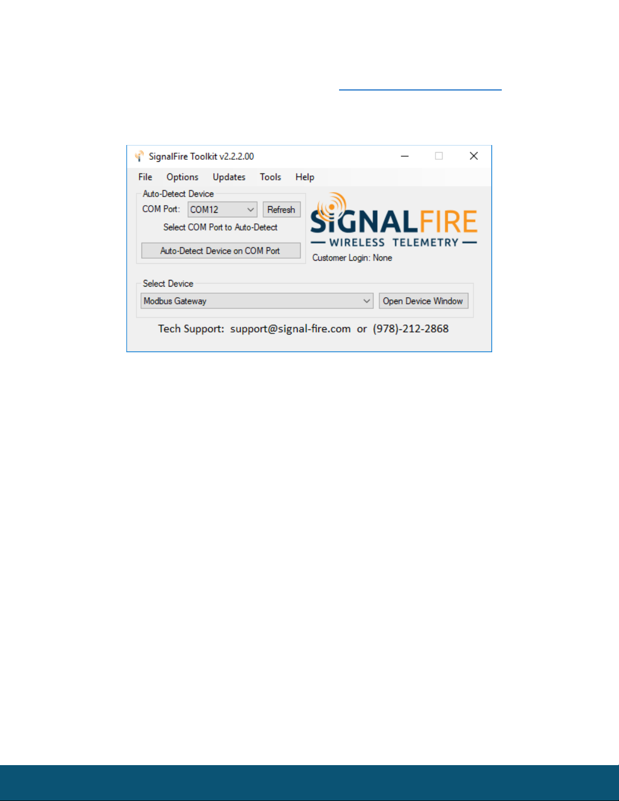
Using the SignalFire Toolkit
The SignalFire Toolkit application can be downloaded at www.signal-fire.com/customer after
registering a free account. After installation, launch the software and the main toolkit window will
open:
Select the COM port associated with the DIN Gateway and click “Auto-Detect Device on COM Port.”
This will open the device configuration window, where all device settings can be configured.
Rev 1.0 SignalFire Telemetry
7
Network Setting
The network is set using the SignalFire Toolkit. There can only be one Gateway per
network/group/encryption combination, otherwise they will conflict. In a system with multiple
Gateways, each Gateway must be on a separate network/group/encryption combination. The
network, network group, and encryption key settings must match those of its nodes for them to
communicate.
Encryption
To protect your over-the-air data and prevent tampering, SignalFire networks come with encryption.
The DIN Gateway v2 comes with “signalfire” set as the default encryption key.
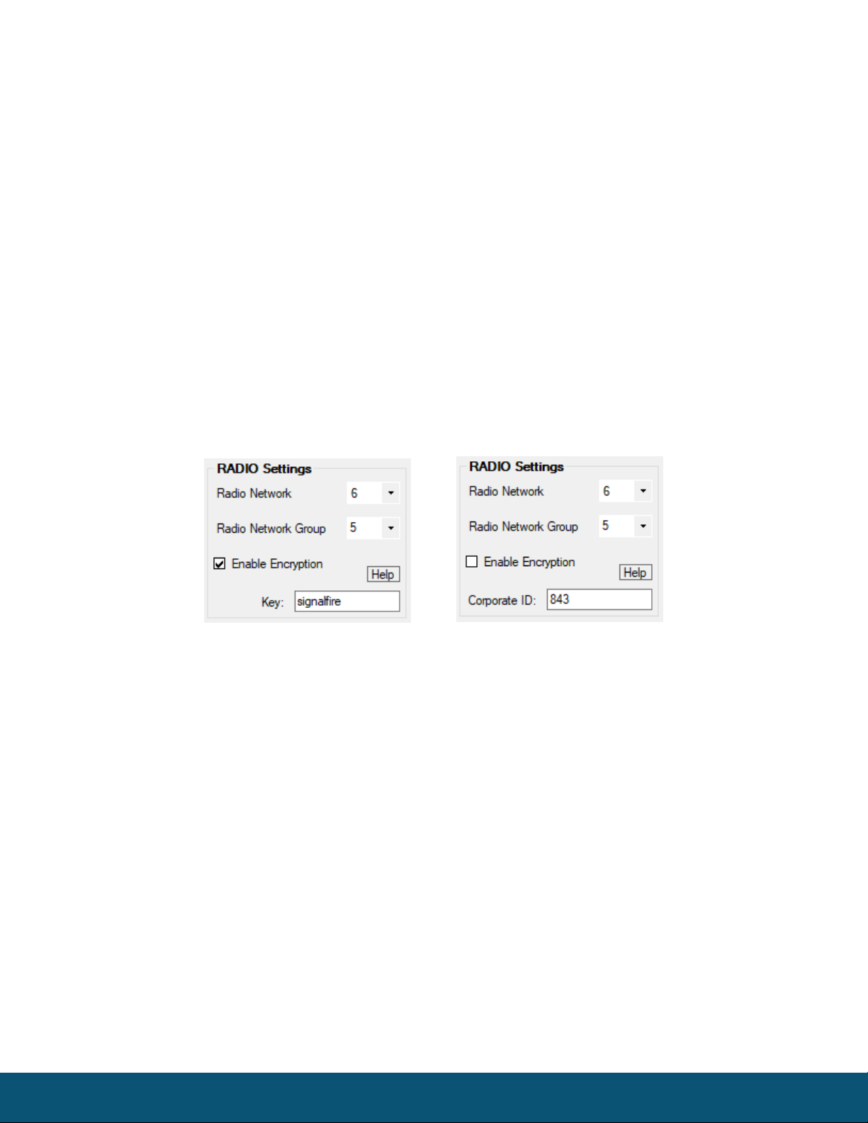
Existing legacy networks may use a Corporate ID, but can be switched over to use an encryption key if
the firmware and ToolKit are up to date. To set up a Gateway on a legacy network using Corporate ID,
click the checkbox labeled Enable Encryption and the setting will change from “Key” to “Corporate ID”.
Radio settings box with and without encryption enabled. For more details, click the Help button.
It is also possible to hide your encryption key so it cannot be read. This is the most secure option, but
if you forget your key, there is no way to recover it – you must reset the key on every device on its
network. To enable this option, select Set Encryption Key Unrecoverable under the Settings menu.
Rev 1.0 SignalFire Telemetry
8
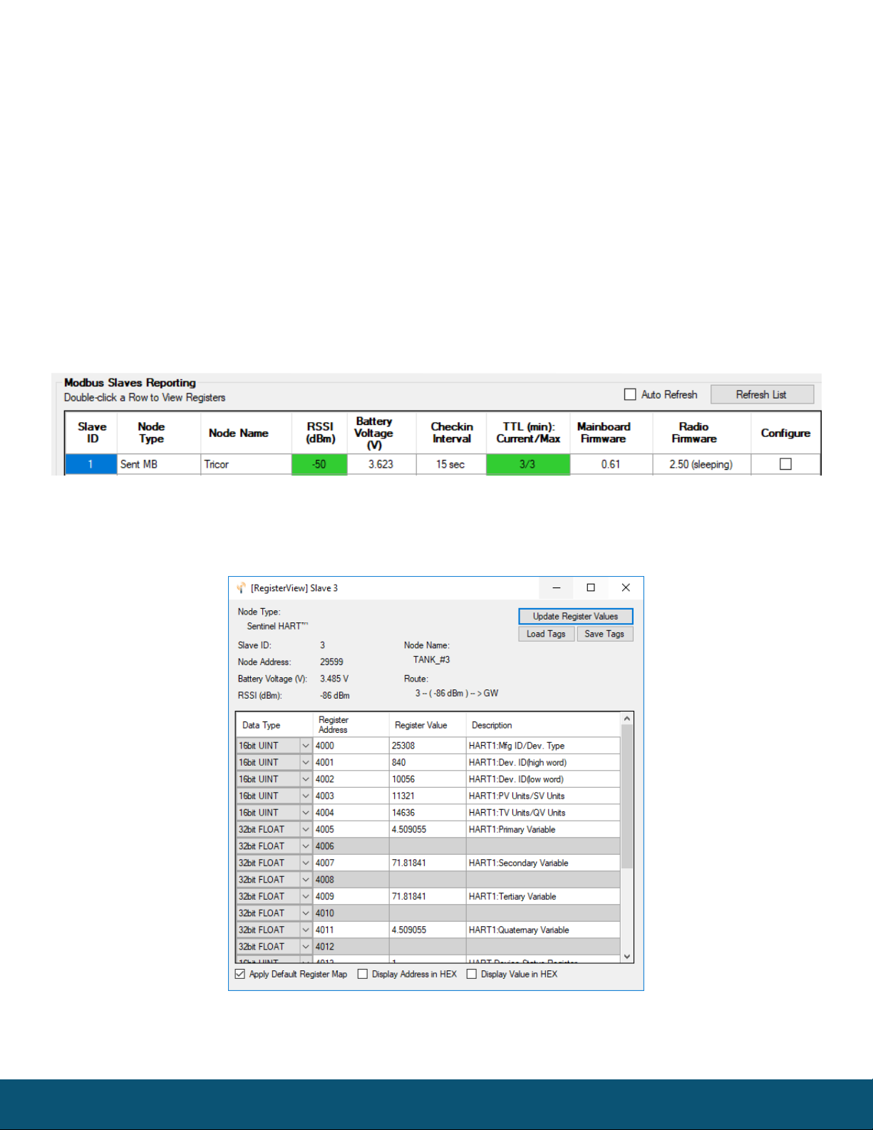
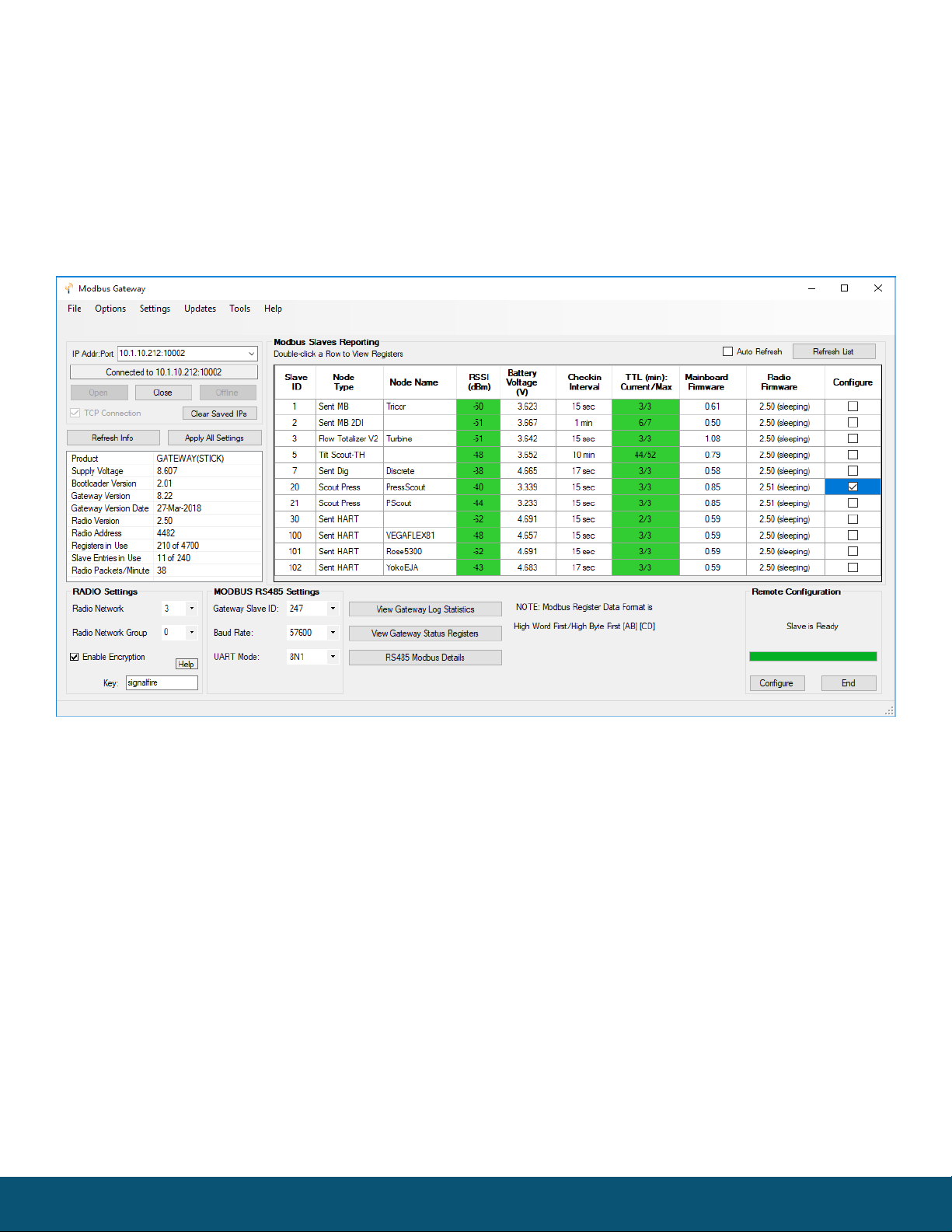
Checking Remote Nodes
If one or more remote nodes are configured with the correct network settings, they will send their
data to the gateway. Clicking Refresh List will populate the list with all connected remote nodes. The
gateway displays the node type, node name (if it has been set), RSSI signal strength, check-in interval,
the Time-To-Live (TTL), and the node’s radio and main firmware versions.
The RSSI and TTL values are color coded (Green, yellow, orange, red) to indicate relative link quality of
a node. The ‘TTL Current’ indicates the number of minutes remaining until the node will be timed out
of the gateway if no updates are received. The ‘TTL Max’ indicates the maximum TTL for that node
and is equal to the node’s check-in interval times 5 plus 2. The ‘TTL Current’ will reset to the ‘TTL Max’
each time an update is received from that node. The ‘TTL Current’ will decrement once a minute.
Double clicking on one of the nodes in the list will bring up additional detail including the register
data from the remote node.
Rev 1.0 SignalFire Telemetry
9
Remote Node Configuration
The SignalFire Gateway allows configuration changes to be made to any of the connected
SignalFire remote nodes wirelessly.
To start a remote configuration session with a remote node, select the check-box next to the node to
configure.
If the device has a non-sleeping radio the remote configuration session will be ready
immediately. If it is a sleeping device, you must wait for the node to either check-in or send a
“beacon” so that it can be commanded into configuration mode. The Sentinel nodes send a
beacon every two and a half minutes, while all other sleeping nodes send a beacon every five
and a half minutes. When the device has entered a remote configuration session you will see a
message indicating the slave is ready. Click Configure to open the configuration window (image on
next page).
Rev 1.0 SignalFire Telemetry
10
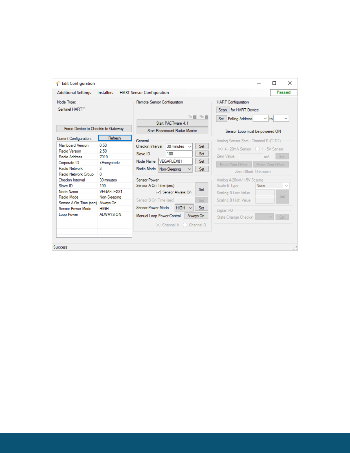
Make any necessary changes and click the corresponding Set button to save the changes.
When finished with the configuration, close the configuration window and then click the End
button in the Gateway window to end the session. The session will also automatically time-out
after 15 minutes of inactivity and the Node will resume normal operation.
Example Remote Configuration Window
Further information on how to remotely configure a HART device through the ToolKit using PACTware
can be found in the “Remote HART Sensor Configuration Manual”.
Remote Modbus Sticks and Sentinel-Modbus (non-sleeping radio only) Nodes
Remote nodes that have been pre-configured forward their set of registers to the Modbus gateway
on a pre-defined schedule (1 minute to 5 minutes is typical). The register data is then buffered in the
gateway and is available to be read by the RTU at any time.
If a Modbus request is received by the gateway for a Modbus ID and address for which buffered data
does not exist, but the Modbus ID is known, the Modbus request will be forwarded to the remote
Modbus node over the SignalFire network. The response is returned to the RTU.
Table des matières
Autres manuels SignalFire Porte


Manuels Porte populaires d'autres marques

LST
LST M500RFE-AS Manuel utilisateur

Kinnex
Kinnex Media Gateway Manuel utilisateur

2N Telekomunikace
2N Telekomunikace 2N StarGate Manuel utilisateur

Mitsubishi Heavy Industries
Mitsubishi Heavy Industries Superlink SC-WBGW256 Manuel utilisateur

ZyXEL Communications
ZyXEL Communications ZYWALL2 ET 2WE Manuel utilisateur

Telsey
Telsey CPVA 500 - SIP Manuel utilisateur


