Side-Power S-linkControl Panel PJC211 Manuel utilisateur
Keep this
manual onboard !
Installation and user's manual
EN
Made in Norway
©Sleipner Motor AS 2013
SLEIPNER MOTOR AS
P.O. Box 519
N-1612 Fredrikstad
Norway
Tel: +47 69 30 00 60
Fax: +47 69 30 00 70
www.side-power.com
sidepower@sleipner.no
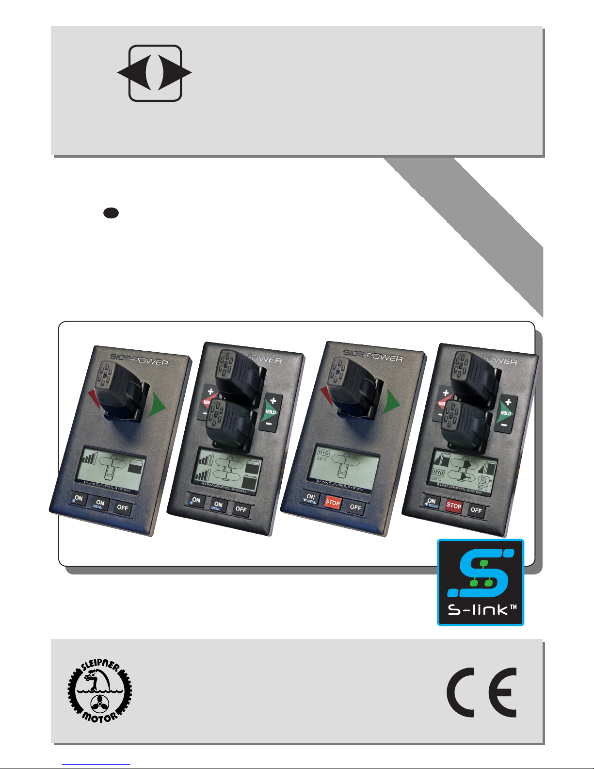
PJC211/212/221/222
S-link Control Panel
SIDE-POWER
Thruster Systems
v 2.0.2

2
PJC211/212/221/222 2.0.2 - 2013
DO NOT connect any other control equipment to the S-link controlled products except
Side-Power original S-link products or via a Side-Power supplied interface product made
for interfacing with other controls. Any attempt to directly control or at all connect into
the S-link control system without the designated and approved interface, will render all
warranties and responsibilities for the complete line of Side-Power products connected
void and null. If you are interfacing by agreement with Sleipner and through a designated
and approved interface, you are still required to also install an original Sidepower control
panel to enable efcient troubleshooting if necessary
DECLARATION OF CONFORMITY
We, Sleipner Motor AS
P.O. Box 519
N-1612 Fredrikstad, Norway
declare that this product with accompanying
standard remote control systems complies with
the essential health and safety requirements
according to the Directive 89/336/EEC of 23
May 1989 amended by 92/31/EEC and
93/68/EEC.
Product Features................................................................................................................................................................................. 3
Panel layout ........................................................................................................................................................................................ 4
Panel layout ........................................................................................................................................................................................ 5
Display in normal use ......................................................................................................................................................................... 6
Display when alarms ........................................................................................................................................................................... 7
Setup procedure.................................................................................................................................................................................. 8
Menu system ....................................................................................................................................................................................... 9
Alarm descriptions ............................................................................................................................................................................ 16
S-link system example....................................................................................................................................................................... 18
Measurements / Cut-out template ..................................................................................................................................................... 19
Connections for external buzzer........................................................................................................................................................ 19
CONTENTS
3
PJC211/212/221/222 2.0.2 - 2013
PJC-211/212/221/222
Control panel with S-link™CAN-bus connection
Product features
• For proportional thruster control with DC, AC and Hydraulic Thrusters (Hydraulic thrusters PJC-221/222 only).
• Finger tip control speed control with purpose designed joysticks
• Hold - function for easy docking, runs thrusters at selected power (Dual joysticks PJC-212/222 only)
• Back-lit LCD display with instant feedback
- System status / alarms
- Amount of thrust & direction of thrust
• Interactive multi-language menus
• CAN-Bus communication with thrusters and accessories
• Plug & play cables with compact connectors
• Diagnostics and system setup via panel
• Built-in audible alarm “buzzer”
• Connector for external “buzzer”/loud audible alarms
• Supports Side-Power retractable thrusters with or
without Speed Control
4
PJC211/212/221/222 2.0.2 - 2013
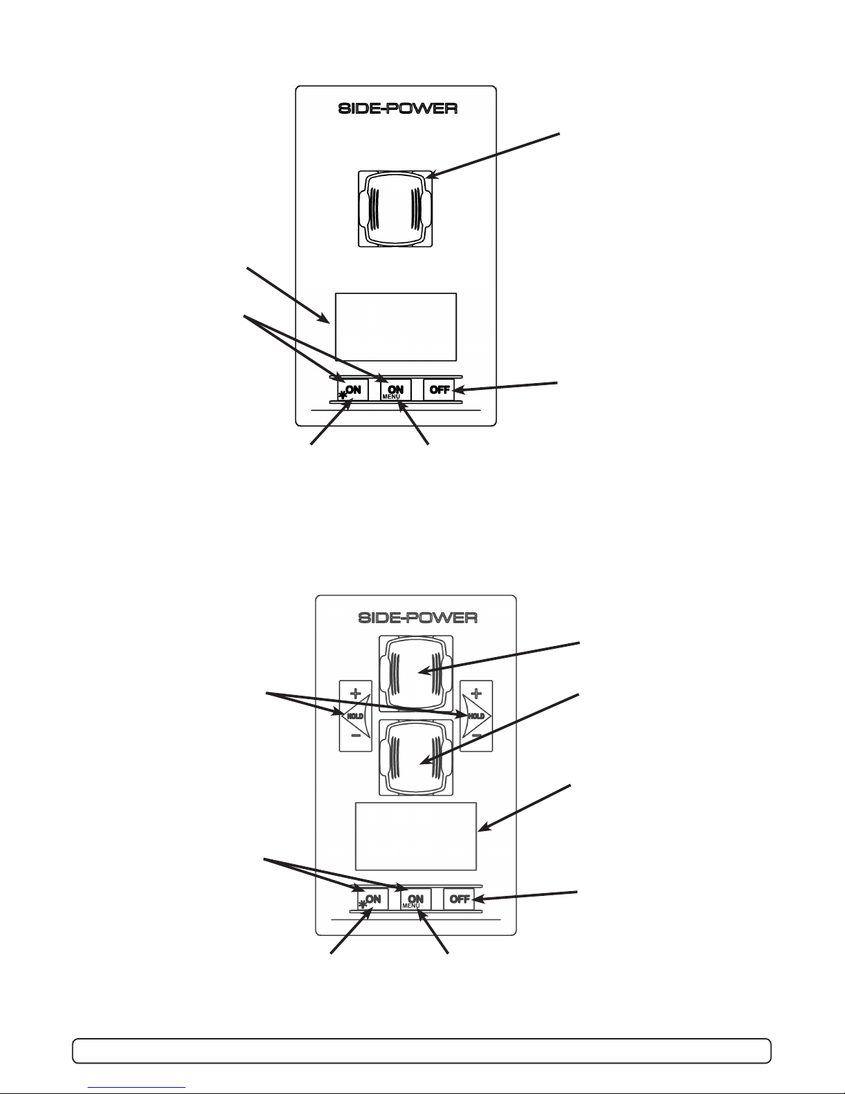
MENU
Speed control joystick for
bow thruster
Speed control joystick for
stern thruster
Information display, see
following pages for
details.
Press both “ON” buttons
simultaneously to
activate control panel.
Press to change
between day and
night light
Press and hold for 3
seconds to access
menu system and
choose items in menus
Press to de-activate
control panel or cancel or
go back in menu system
or mute internal alarm
buzzer
MENU
MENU
Speed control joystick for
thruster
Information display, see fol-
lowing pages for
details.
Press both “ON” buttons
simultanously to activate
control panel.
Press to change
between day and
night light
Press and hold for 3
seconds to access menu
system and choose items
in menus
Press to de-activate
control panel or cancel or
go back in menu system
or mute internal alarm
buzzer
Panel Layout, PJC-211
Panel Layout, PJC-212
Holding function for auto-
running of bow and stern
thrusters together in the
direction of the arrows at
selected power
Press “+” for more and “-”
for less power (6 steps).
If any control unit are
running the thruster in op-
posite direction to the hold
function, the hold function
will be deactivated.
5
PJC211/212/221/222 2.0.2 - 2013
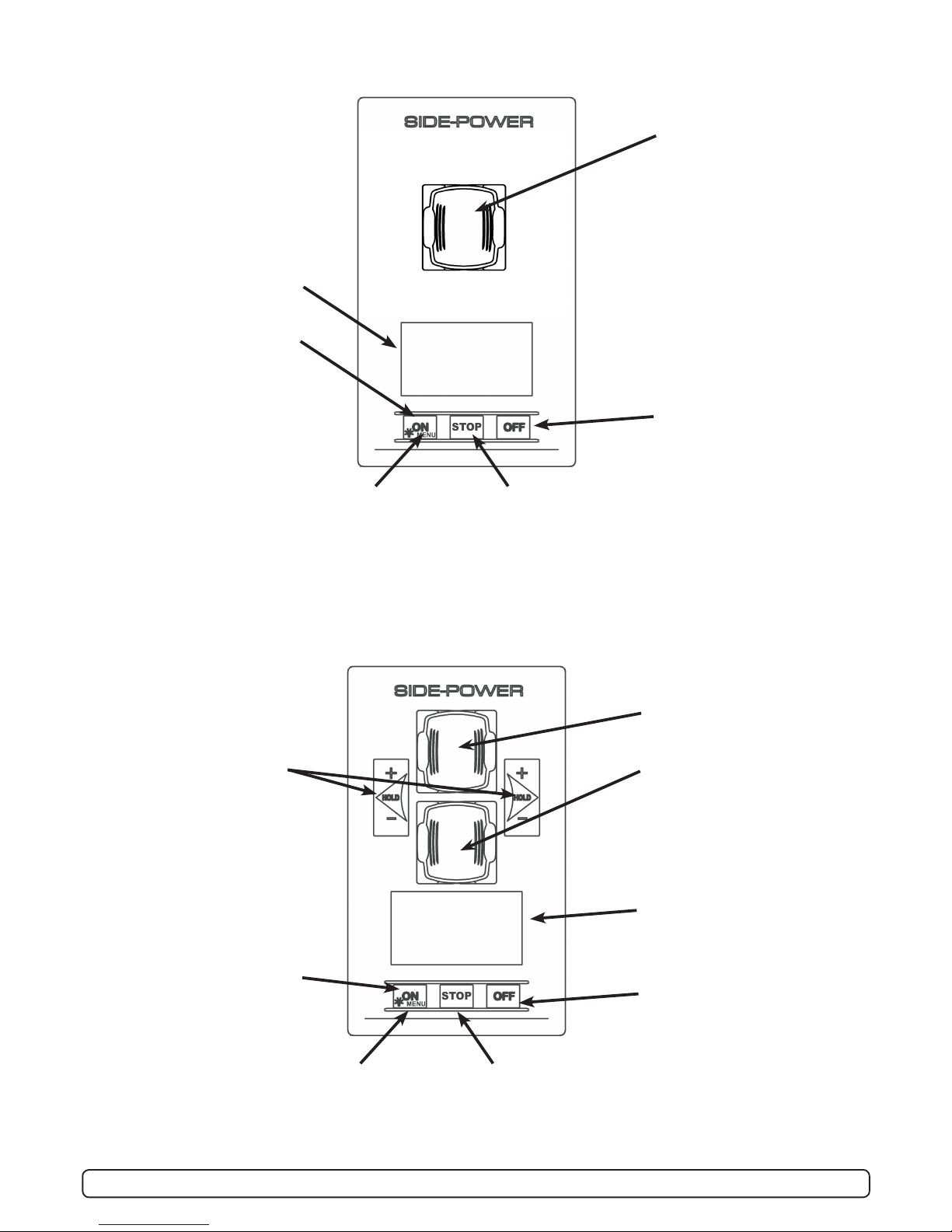
STOP
front s_v strek_PJC222.pdf 1 04.11.2010 11:05:34
MENU
Speed control joystick for
thruster
Information display, see fol-
lowing pages for details.
Press and hold “ON”
button for 1 second to
activate control panel.
Press to change
between day and
night light.
Press and hold for
3 seconds to enter
menu system
Emergency stop
button
Press to de-activate
control panel or cancel or
go back in menu system.
Mute buzzer alarm
STOP
front s_v strek_PJC222.pdf 1 04.11.2010 11:05:34
Speed control joystick for
bow thruster
Speed control joystick for
stern thruster
Holding function for auto-
running of bow and stern
thrusters together in the
direction of the arrows at
selected power
Press “+” for more and “-”
for less power (6 steps).
If any control unit are
running the thruster in op-
posite direction to the hold
function, the hold function
will be deactivated.
Information display, see
following pages for details.
Press and hold “ON” button
for 3 seconds to activate
control panel.
Press to change
between day and
night light.
Press and hold for
3 seconds to enter
menu system
Emergency stop
button
Press to de-activate
control panel or cancel or
go back in menu system
Panel Layout, PJC-221
Panel Layout, PJC-222
6
PJC211/212/221/222 2.0.2 - 2013
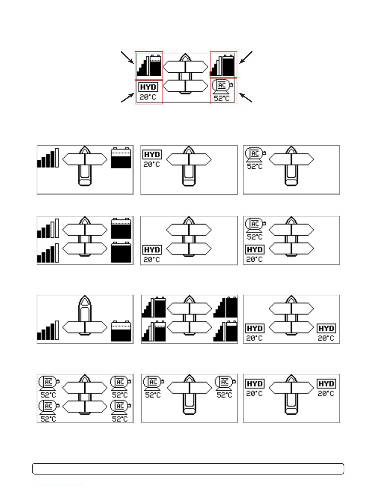
Status indicators for bow
thruster. (Port bow thruster in
a dual bow thruster setup)
Runtime indicator will be
shown here in a single DC
electric bow thruster setup
Status indicators for stern
thruster. (Port bow thruster in
a dual stern thruster setup)
Runtime indicator will be
shown here in a single DC
electric stern thruster setup
Status indicators for starboard
bow thruster. Only shown in a
dual bow thruster setup.
Battery indicator will be shown
here in a single DC electric bow
thruster setup
Status indicators for starboard
stern thruster. Only shown in a
dual stern thruster setup.
Battery indicator will be shown
here in a single DC electric stern
thruster setup.
DISPLAY IN NORMAL USE:
BOW
STERN
BOW-STB
STERN-STB
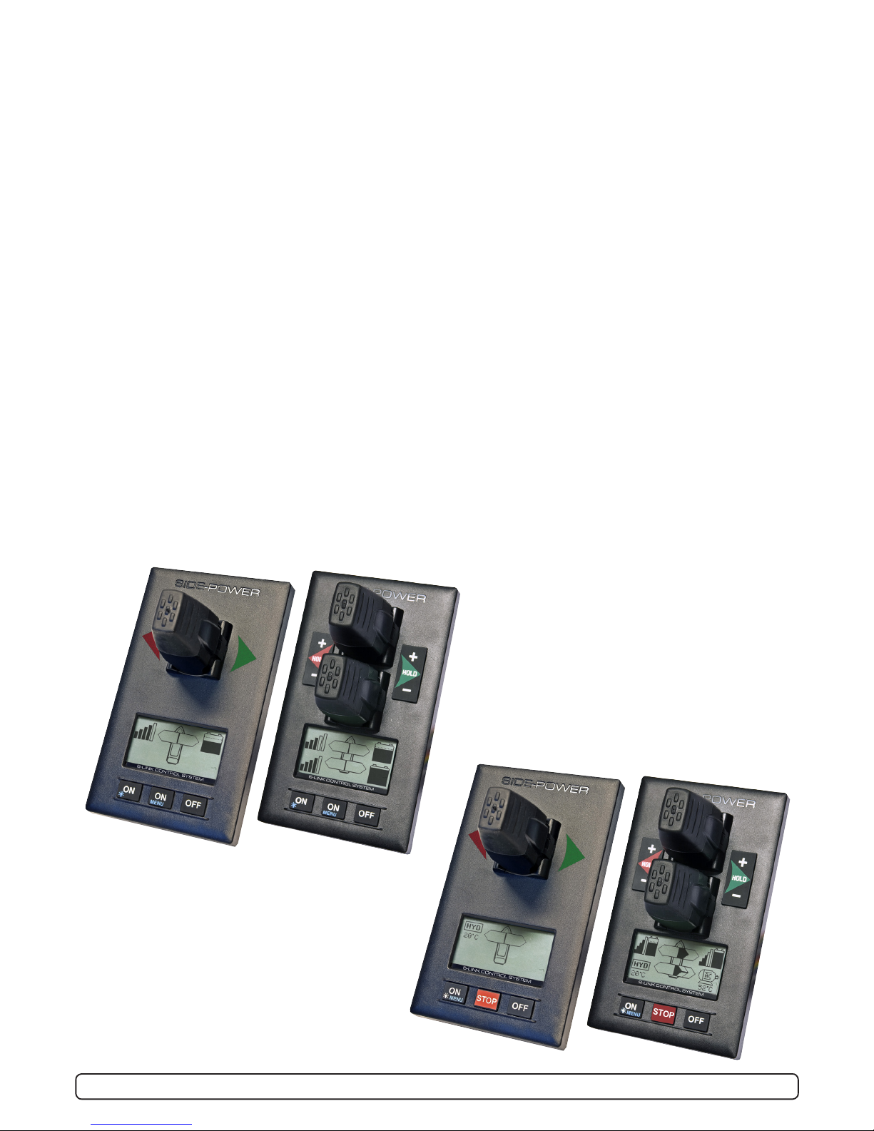
Examples of display for different panel applications:
PJC211/221:
DC Electric Bow thruster
PJC221:
Hydraulic Bow thruster
PJC221:
AC Electric Bow thruster
PJC212/222:
DC Electric Bow thruster
DC Electric Stern Thruster
PJC222:
Hydraulic Bow thruster
Hydraulic Stern Thruster
PJC222:
AC Electric Bow thruster
Hydraulic Stern Thruster
PJC211/221:
DC Electric Stern thruster PJC212/222:
Dual DC Electric Bow thrusters
Dual DC Electric Stern thrusters
PJC222:
Dual Hydraulic Bow thrusters
Dual Hydraulic Stern thrusters
PJC222:
Dual AC Electric Bow thrusters
Dual AC Electric Bow thrusters
PJC221:
Dual AC Electric Bow thrusters
PJC221:
Dual Hydraulic bow thrusters
7
PJC211/212/221/222 2.0.2 - 2013
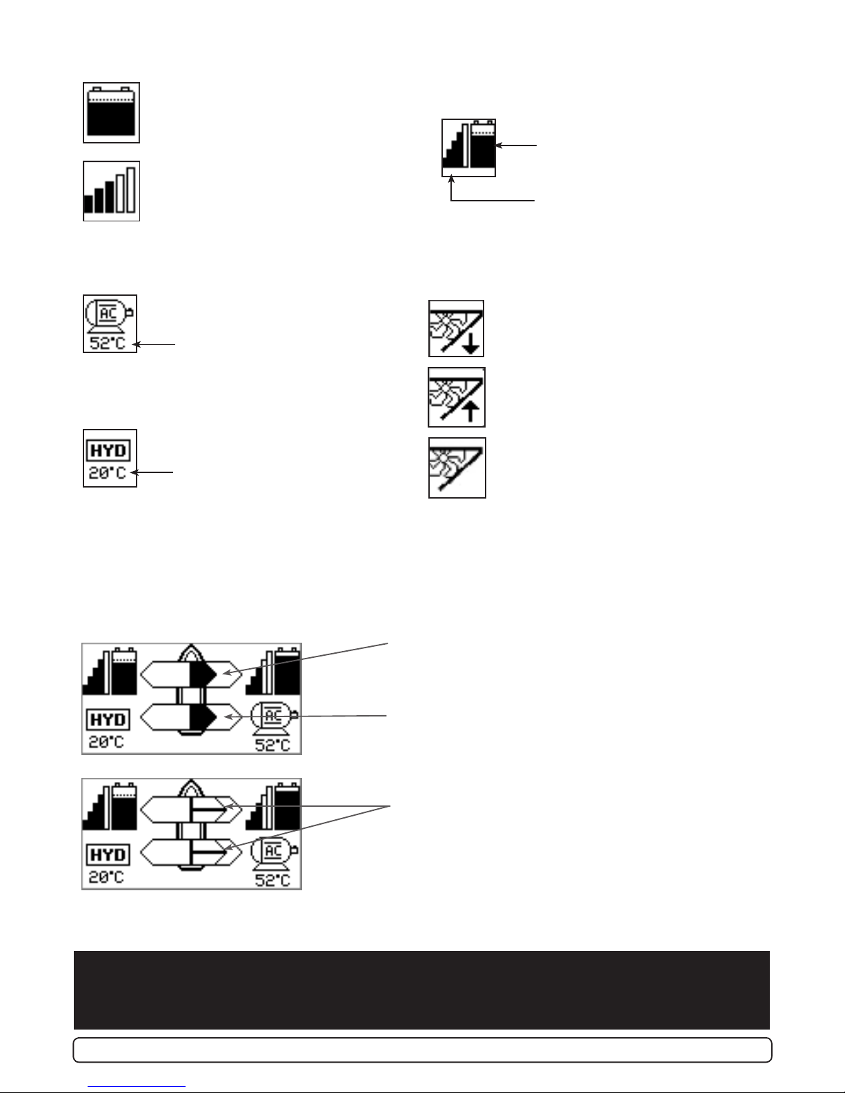
Battery indicator.
From 8.5V to 12V for 12V thrusters,
15V to 24V for 24V thrusters
Motor temperature indicator.
From 70°C to 130°C
INDICATORS FOR DC Thrusters:
INDICATORS FOR AC Thrusters:
INDICATORS FOR Hydraulic Thrusters:
Motor temperature indicator.
Hydraulic oil temperature indicator.
INDICATORS FOR Retractable Thrusters:
Symbol shown when the thruster deploys
Symbol shown when the thruster retracts
Symbol shown when the thruster is in
position OUT
When the thruster is deployed and no
input is given via the joysticks/buttons
over a 10 second period, the panel will
give a audible signal every 10th second
to tell that the truster is still deployed.
Thrust power and direction, Bow thruster(s)
Input from bow joystick on this panel.
The thrust indicator will be shown in this position on a single
joystick panel if the thruster is dened as a bow thruster
Indicating amount of thrust set by other control units in the
system, i.e additonal PJC panels, 8700 Retract panel, input
via 8730 S-link external switch interface, S-link remote con-
trol etc.
If two or more units is set to run the thruster in
opposite direction, this information will not be shown.
FIRST TIME SETUP
After installation of a S-link thrusters system, a System Setup procedure to setup control panels, thrusters and
additional equipment must be completed (ref. procedure on page 10) before the system can be used.
Thrust power and direction, Stern thruster(s)
Input from stern joystick on this panel
The thrust indicator will be shown in this position on a single
joystick panel if the thruster is dened as a stern thruster.
Battery indicator.
From 8.5V to 12V for 12V thrusters,
15V to 24V for 24V thrusters
Motor temperature indicator.
From 70°C to 130°C
Symbol shown when a DC Thruster is
used in a dual bow or dual stern setup:
INDICATORS showing thrust direction and amount:
8
PJC211/212/221/222 2.0.2 - 2013
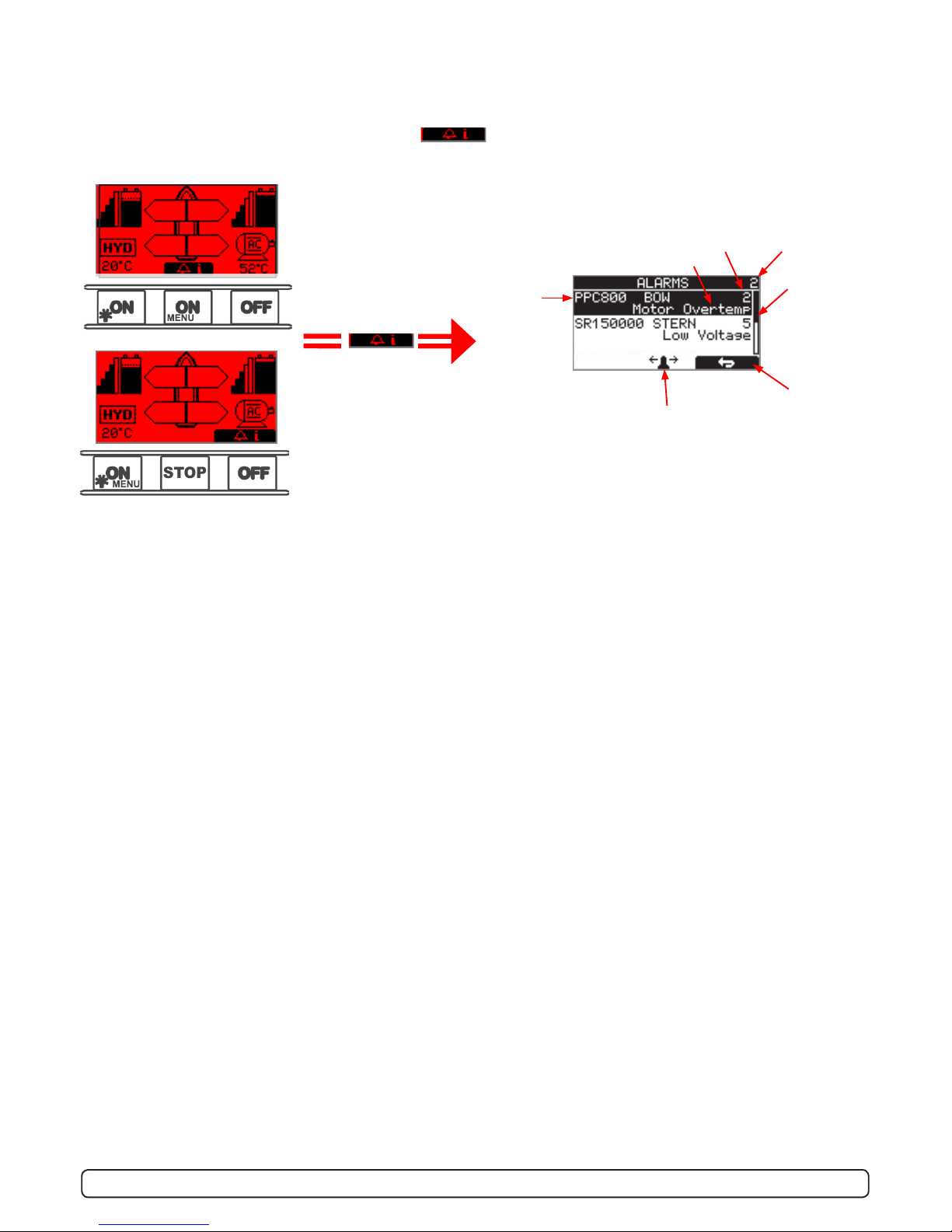
DISPLAY WHEN ALARMS:
When there is a problem or a fault, the panel will show this alarm situation by changing LCD display backlight to
red color.
The panel will also change to show “Alarm Info” on the bottom of the screen, indicating that by press-
ing the corresponding button below, you will get information about what the problem is (examples below).
MENU
Voltage below 9.3V/17.5V (12V/24V system) or temperature above 85oC (80oC for PPC800 FW V1.013 or
older/ SR150000 FW V1.006 or older): Single short beep every 2.4 seconds
Voltage below 8.9V/16.3V (12V/24V system) or temperature above 100oC (90oC for PPC800 FW V1.013 or
older/ SR150000 FW V1.006 or older): Two short beeps every 2.4 seconds
Voltage below 8.5V/15V (12V/24V system) or temperature above 115oC (100oC for PPC800 FW V1.013 or
older/ SR150000 FW V1.006 or older): Red backlight in display and continous short beeps.
If one or more of the thrusters enters an alarm state - Voltage below 8 Volts (both 12 and 24 Volt sys-
tems) or temperature above 130oC (110oC for PPC800 FW V1.013 or older/ SR150000 FW V1.006 or older):
Continuous beeps, and the “HOLD” function will be cancelled and both thrusters will stop. Temperature must drop
below 115oC (100oC for PPC800 FW V1.013 or older) before the thruster can be operated again.
STOP
front s_v strek_PJC222.pdf 1 04.11.2010 11:05:34
(Button below this
symbol pressed)
No. of alarms
Alarm code
Alarm description
Reset alarm
and Return
Use joystick to scroll if
more than two alarms
Scroll bar
Name and
location of
device
Refer to Alarm code overview/table on pages 18-19 for
full description on the different alarm codes.
When using the “HOLD” function,
the internal and external (if tted) buzzer will give the following warning signals:
9
PJC211/212/221/222 2.0.2 - 2013
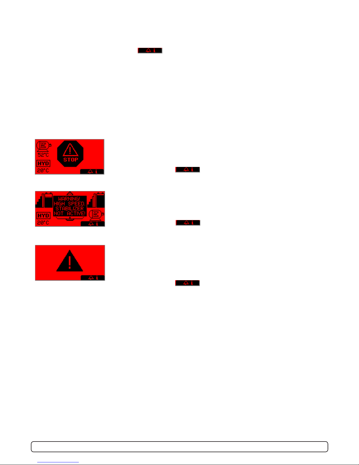
STOP BUTTON
Pressing the STOP button on a hydraulic panel will operate the dump valve and
the thruster will stop. NB: FOR EMERGENCY USE ONLY
Panel will not run thrusters.
Pressing button below will mute buzzer alarm at all panels and show
the alarm info screen.
SPECIFIC ALARMS
WARNING! HIGH SPEED. STABILIZER NOT ACTIVE!
(Only for yachts equipped with a Side-Power Stabilizer system)
Warning will show when yacht is driven at high speed with stabilizer system inac-
tive. Please refer to the Stabilizer ECU manual for speed settings.
Pressing button below will mute buzzer alarm at all panels and show
the alarm info screen.
ALARMS (AC & HYDRAULIC THRUSTERS):
When there is a problem or a fault, the panel will show this alarm situation by the LCD display in red color.
All alarms will show in display when panel is turned OFF. This requires the S-link and other system devices has
power. Critical alarms are also trigging internal and external buzzer (a long beep every 2 seconds). The buzzer can
be silenced by pushing the button below , this will also silence all other panels in the system
Critical alarms: LOW OIL LEVEL, HIGH OIL TEMPERATURE, EMERGENCY STOP, HIGH SPEED STABILIZER NOT AC-
TIVE and HYDRAULIC AC MOTOR POWER PACK OVERTEMP, AC THRUSTER OVERTEMP, AC THRUSTER FAIL, STABI-
LIZER FAULT
For safety!
When oil pressure goes below 10bar, the HOLD function are deactivated.
ALARM SHOWN ON INACTIVE PANELS!
This screen will be shown on inactive panels if any of the following critical alarms
occur:
LOW OIL LEVEL, HIGH OIL TEMPERATURE, HYDRAULIC AC MOTOR POWER PACK
OVERTEMP, AC THRUSTER OVERTEMP, AC THRUSTER FAIL
Pressing button below will mute buzzer alarm at all panels and show
the alarm info screen.
10
PJC211/212/221/222 2.0.2 - 2013
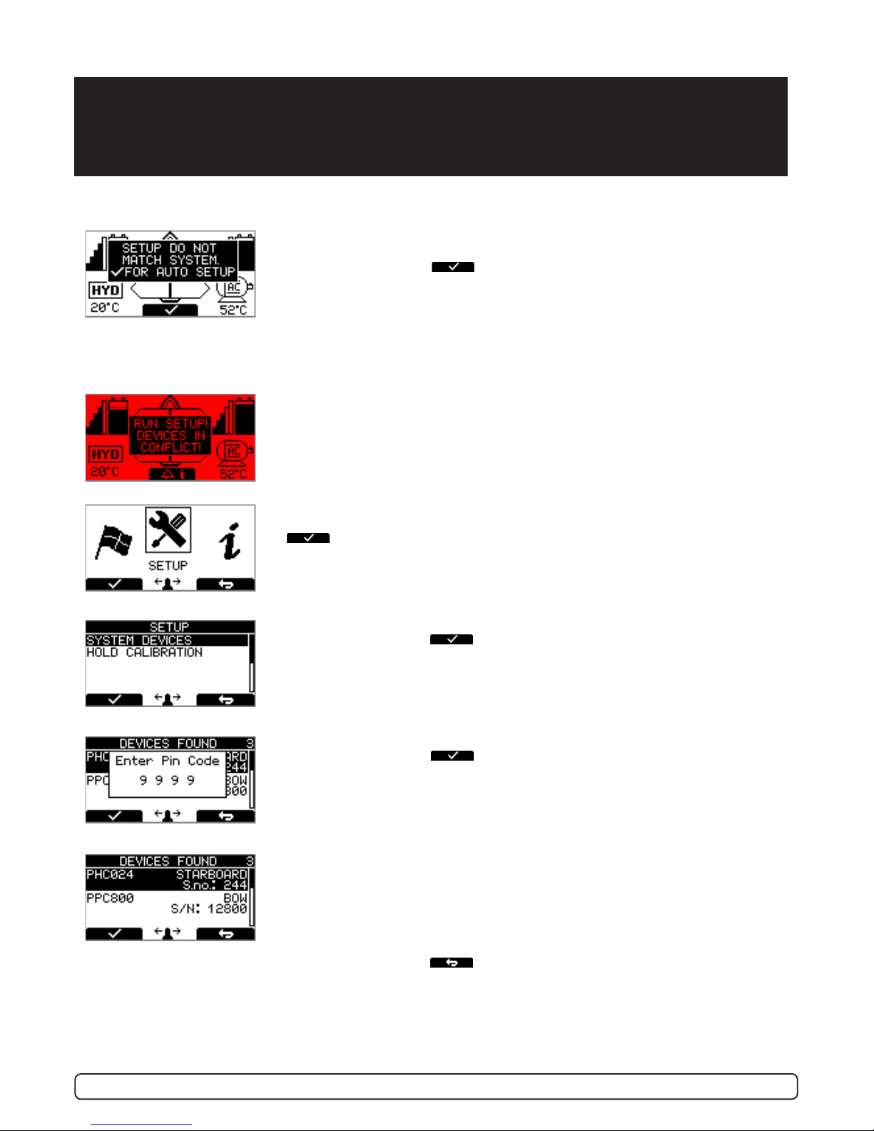
SETUP PROCEDURE
RUN SETUP! DEVICES IN CONFLICT!
Detectet devices in conict. Two or more thrusters dened as same instance
(bow/stern/bow STB/Stern STB). Run Setup procedure to correct.
Thrusters can not be operated until seup is completed.
SETUP DO NOT MATCH SYSTEM. FOR AUTO SETUP
New devices found. Not in conict with other devices.
Press button below the -symbol to auto setup.
Thrusters can not be operated to auto setup is completed.
The setup procedure requires knowledge of the serial numer and location of all the S-link
devices.
Write this down in the form on the last page to have the information at hand when doing a
manual setup.
Press and hold the button marked “MENU” for 3 seconds to enter the menu sys-
tem. Use the (stern) joystick to select “SETUP”, Press button below the
-symbol to enter the”SETUP”-menu.
Use the (stern) joystick to select “SYSTEM DEVICES”,
Press button below the -symbol to enter the”SYSTEM DEVICES”-menu.
Use the (stern) joystick to set the pin code one number at the time,
press button below the -symbol to jump to next number and conrm.
The pin code is “9 9 9 9”.
NOTE: Re-entering the SYSTEM DEVICES menu within 15 minutes does not
require entering PIN code
The devices found in the system is now displayed with their instance and serial
number.
Go through all devices and make sure that they are set to the correct instance
and function (refer to detailed instructions in the SETUP section of “Menu
System”-chapter).
Press button below the -symbol to save setting and return to “Setup”-
Menu.
At the rst startup of a new system, one of the two screens below will be shown:
Autres manuels pour S-linkControl Panel PJC211
2
Ce manuel convient aux modèles suivants
3
Table des matières
Autres manuels Side-Power Panneau de contrôle

Side-Power
Side-Power S-link PJC-212 Manuel utilisateur

Side-Power
Side-Power 8940 Manuel utilisateur

Side-Power
Side-Power S-linkControl Panel PJC211 Manuel utilisateur

Side-Power
Side-Power S-link PJC-212 Manuel utilisateur

Side-Power
Side-Power PJC322 Manuel utilisateur

Side-Power
Side-Power 8950G Manuel utilisateur

Side-Power
Side-Power PJC 212 Manuel utilisateur

Side-Power
Side-Power S-linkControl Panel PJC211 Manuel utilisateur

Side-Power
Side-Power S-linkControl Panel PJC222 Manuel utilisateur

Side-Power
Side-Power S-linkControl Panel PJC221 Manuel utilisateur


