Sicunet Neptune Series Manuel utilisateur

Neptune Series Access Control Systems
Installation Instructions
for 1 Door Systems and 2 & 4 Door Systems
with Integrated Power Supplies
Document Number: 100100 REV A
Installation Instructions for 1 Door and 2 & 4 Door Systems with Integrated Power Supply Page 1

Table of Contents
Notifications...................................................................................................................................................4
Copyright...................................................................................................................................................4
Approvals...................................................................................................................................................4
Notice.........................................................................................................................................................4
Introduction....................................................................................................................................................5
Access Control Overview..........................................................................................................................5
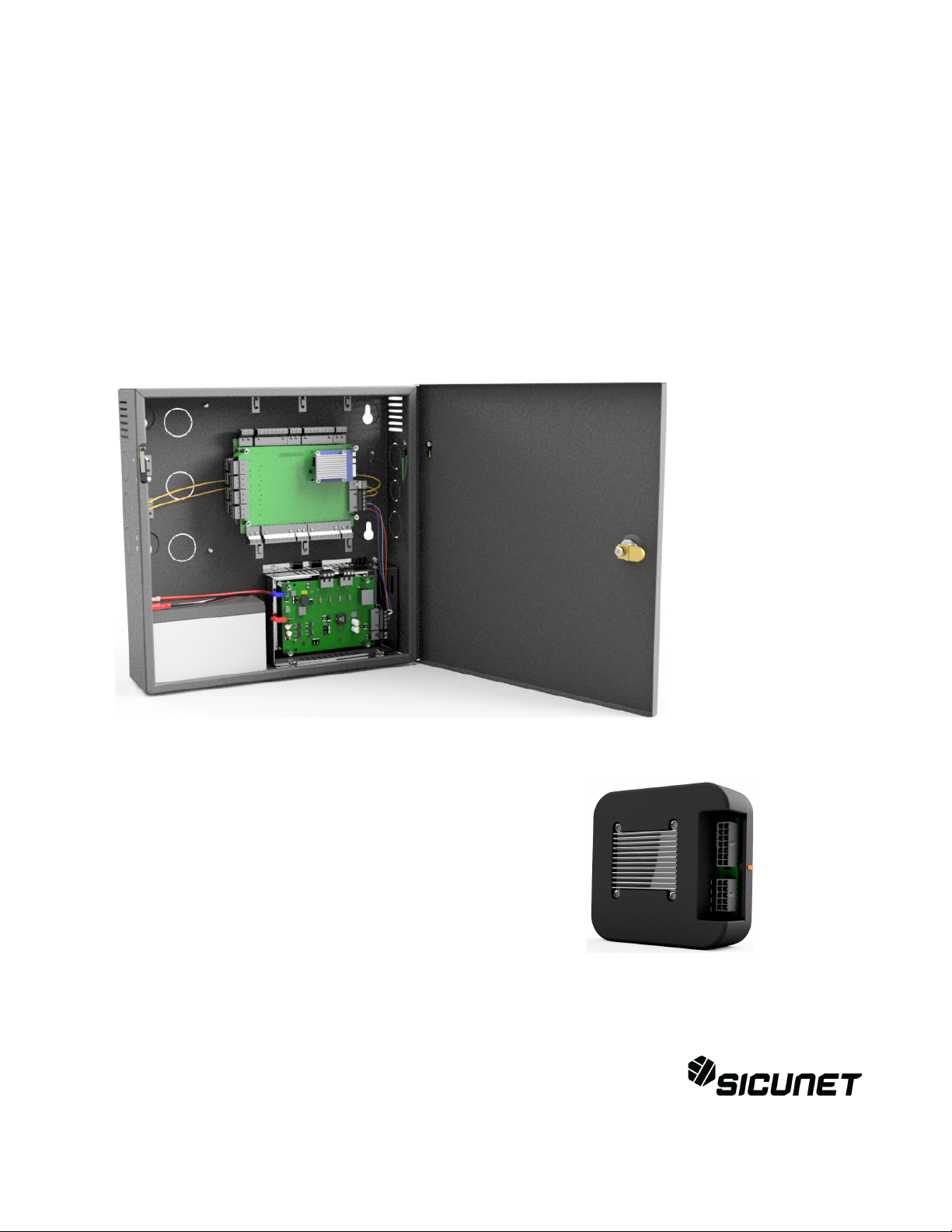
System Overview.......................................................................................................................................5
2 4 Door Systems Specifications................................................................................................................6
Installation of 2 4 Door Systems................................................................................................................7
Installation Check List...............................................................................................................................7
Locating the Controller for Installation.....................................................................................................7
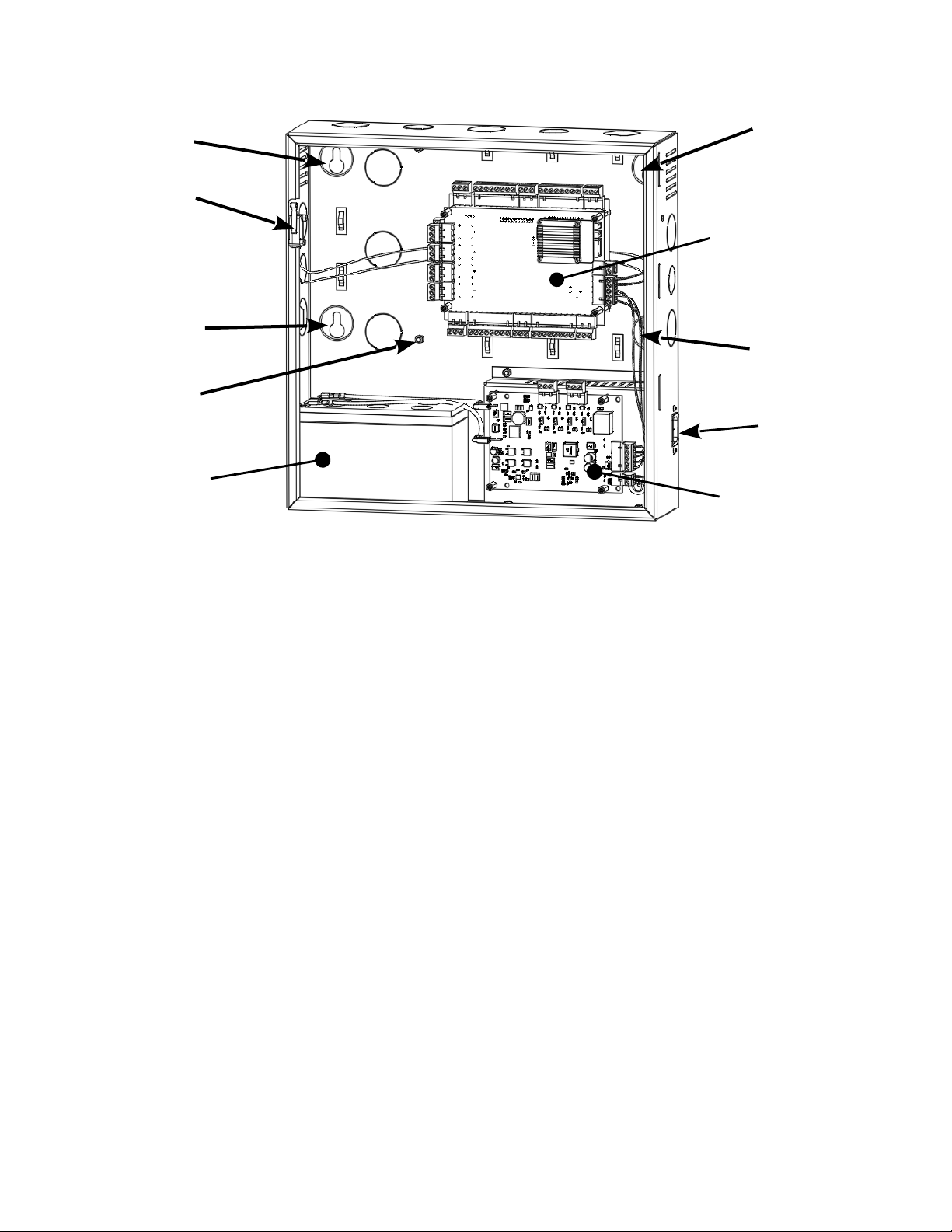
Mounting the Metal Enclosure – 2 4 Door Systems..................................................................................8
Tamper Detection......................................................................................................................................9
System Power............................................................................................................................................9
Power Fault Detection...............................................................................................................................9
Door Lock Power.......................................................................................................................................9
Fire Release Input....................................................................................................................................10
Battery Connection..................................................................................................................................10
Battery Warnings.....................................................................................................................................10
Input Power Connector............................................................................................................................11
Controller Power, Power Fault and Fire Cutout Connector.....................................................................11
Output Power Connectors........................................................................................................................12
Power Connection....................................................................................................................................13
Calculating Estimated Standby Time......................................................................................................13
Controller Features – 2 4 Door Systems..................................................................................................14
Controller Hardware Identification.........................................................................................................14
Controller Inputs......................................................................................................................................14
Controller Connectors..............................................................................................................................15
Input Wiring.............................................................................................................................................15
Request to Exit and Door Position Connectors.......................................................................................16
Power, Power Fault and Tamper Connector............................................................................................17
Controller Outputs...................................................................................................................................20
Output Wiring Requirements...................................................................................................................21
Door and Auxiliary Output Connectors...................................................................................................21
Adding 2 Door Expansion.......................................................................................................................23
1 Door System Specifications......................................................................................................................24
Installation of 1 Door Systems.....................................................................................................................25
Installation Check List.............................................................................................................................25
Locating the Controller for Installation...................................................................................................25
Mounting the 1 Door System.......................................................................................................................26
Controller Features 1 Door Systems............................................................................................................27
Controller Hardware Identification.........................................................................................................27
Controller Inputs......................................................................................................................................27
Controller Wiring Harnesses...................................................................................................................28
Input Wiring.............................................................................................................................................28
Controller Outputs Power Input..........................................................................................................32
Installation Instructions for 1 Door and 2 & 4 Door Systems with Integrated Power Supply Page 2

Output Wiring Requirements...................................................................................................................33
Powering On and Connecting to a Network.................................................................................................35
Preparing for the Network.......................................................................................................................35
Connecting to the Local Network............................................................................................................36
Adding Clients to Systems......................................................................................................................37
IP Installer................................................................................................................................................38
System Configuration and Programming................................................................................................39
Trouble Shooting..........................................................................................................................................40
Testing, Maintenance and Service................................................................................................................42
Parts List.......................................................................................................................................................42
Contact Warranty Information..................................................................................................................43
Installation Instructions for 1 Door and 2 & 4 Door Systems with Integrated Power Supply Page 3

Notifications
Copyright
Copyright © 2 19, all rights reserved. No part of this document may be reproduced, copied,
adapted or transmitted in any form without written permission from Sicunet, Inc.
Approvals
This equipment has been tested and found to comply with the limits for a Class A digital device,
pursuant to part 15 of the FCC Rules. These limits are designed to provide reasonable
protection against harmful interference when the equipment is operated in a commercial
environment. This equipment generates and can radiate radio frequency energy and if not
installed and used in accordance with the manual, may cause harmful interference. Operation of
this equipment in a residential area is likely to cause harmful interference in which case the user
will be required to correct the interference at their own expense.
This Access Control System is compliant with Level I UL 294 listed devices and must be
installed in a controlled location.
Notice
This manual contains information regarding the basic installation and configuration of the
browser-based Access Control System. It must be read and completely understood before
installation or operation.
It is intended that this unit will be installed by persons trained and qualified to install access
control systems and has the skills and knowledge working with electrical circuits and safety
codes. Important safeguards and instructions in this manual cannot cover all possible situations
and conditions that occur during installation and use and it must be understood that common
sense and caution must be exercised by the person(s) installing, maintaining and operating the
equipment.
Installations must conform to all national and local building and electrical codes.
This manual is for installing 1 Door Systems and 2 & 4 Door Systems ith
integrated po er. Please refer to the appropriate sections for specific
installation instructions for your system.
Installation Instructions for 1 Door and 2 & 4 Door Systems with Integrated Power Supply Page 4

Introduction
Access Control Overvie
Access Control is the selective restriction to a place or resource such as a property, building or
room to authorized persons and is a matter of who, where, and when. An access control system
is used to automate access control using credentials, credential readers, electric door locks and
other devices. Administrators configure the system to determine who is allowed to enter or exit,
where they are allowed to exit or enter, and when they are allowed to enter or exit. When access
is granted, the door is unlocked for a predetermined time and transaction is recorded. When
access is denied, the door remains locked and the attempted access is recorded. Administrators
can then run reports on the recorded transactions to review activity for selected dates and times.
System Overvie
Controller models are available in variety of configurations starting from 1 Door models that
require a separate power supply to 2 & 4 Door models that include an integrated power supply
for the controller and door lock power. Most models can be ungraded after installation with
enhanced features, such as enhanced reporting or more users, using software license keys. All
controllers include tamper and power fault inputs, in and out readers, request to exit and door
position inputs for each door and auxiliary inputs and outputs. All controllers are designed to be
connected to a network using an Ethernet RJ45 connector and configured using the integrated
web server.
Controllers can be configured as either a server or a client. All systems require a server
controller. Some systems have the ability to add additional client controllers to increase the
number of doors, inputs or outputs or control elevators. The software license key is used by the
controller to determine if it is a server or a client. After logging in, the license information about a
can be determined by clicking on the license icon at the bottom of the web page.
Certain models offer a mobile APP that can be used to setup and configure, view logs, lock and
unlock doors and activate threat levels. In addition, some systems also offers a cloud service
that provides a portal where a users or dealer can log into and manage one or many systems
securely.
Client controllers communicate with the server controller via the local area network and are
configured through the server using a web browser on PC connected to the network. Once the
server or client controller is configured, they will function without a network connection or the
PC. The network and PC is only required for setup, configuration and reporting.
Installation Instructions for 1 Door and 2 & 4 Door Systems with Integrated Power Supply Page 5

2 & 4 Door Systems Specifications
General Specifications
Processor Quad Core Cortex, 1.5 GHz
Memory 1GB DDR3 & 8 GB eMMc
Operating System Embedded Linux
Transactions > 45 per Second
System Power Requirements 115VAC @ 1.5A
Operating Temperature 5 ºF to 95ºF (1 ºC to 35ºC)
Enclosure Size (W x H x D) 14.25 x 14.25 x 3.75 in ( 362 x 362 x 95 mm)
Model
2 Door Systems 4 Door Systems
2DM 2DMPL 4DM 4DMPL
Internal Power Supply Controller &
Readers Only
Controller,
Readers & 12V
and 24V DC for
Door Locks
Controller &
Readers Only
Controller,
Readers & 12V
and 24V DC for
Door Locks
Battery Backup Controller &
Readers Only
Controller,
Readers & Door
Lock
Controller &
Readers Only
Controller,
Readers & Door
Lock
Recommended Battery Type
(battery is not included) 12V, 7AH, Sealed Lead Acid
Readers (Wiegand) 4 Total, One In & One Out Reader
for Each Door
8 Total, One In & One Out Reader
for Each Door
Request to Exit (REX) Inputs 2 Total, One for Each Door 4 Total, One for Each Door
Door Position (status) Inputs 2 Total, One for Each Door 4 Total, One for Each Door
Auxiliary Inputs 2 Total, General Purpose 4 Total, General Purpose
Tamper Digital Input Yes, Prewired on Units with Integrated Power
Power Fault Digital Input Yes, Prewired on Units with Integrated Power
Door Lock Outputs 2 Form C Relay, 24V @ 2. A 4 Form C Relay, 24V @ 2. A
Auxiliary Outputs 2 Form C Relay, 24V @ 2. A 4 Form C Relay, 24V @ 2. A
Installation Instructions for 1 Door and 2 & 4 Door Systems with Integrated Power Supply Page 6

Installation of 2 & 4 Door Systems
Installation Check List
The list below provides a logical sequence for installing a system. This list cannot cover all
possible situations and conditions that occur during installation and use and it must be
understood that common sense and caution must be exercised by the person(s) installing,
maintaining and operating the equipment.
✔Calculate the systems power requirement by adding up the power required
for each device connected to the system to make sure the required power
can be provided by the system.
✔Mount the controller in a secure, controlled location
✔Connect the inputs and outputs
✔Connect the readers
✔Connect the door locks and auxiliary outputs
✔Connect power to the controller using a dedicated unswitched, grounded
outlet rated for 115 VAC @ 5 Amps
✔Obtain an IP address, Subnet Mask, DNS and other information from the
network administrator
✔Configure the controller's network settings
✔Connect the controller to the local area network
✔Add optional license keys to upgrade features
Locating the Controller for Installation
Choose a centrally located, secure, clean and dry area near an AC power source. Avoid
mounting the controller within 6 feet of any equipment that may generate electrical interference.
CA TION: The power supply used for the controller must only
be connected to an unswitched, rounded, 115 VAC outlet. If
an unswitched outlet is not available or within 6 feet of the
controller mountin location, have a licensed electrician install
an outlet per local codes. All wirin must be in accordance with
the National Electrical Code, NPFA 70 and all local codes. For
UL installations, the maximum Ethernet cable len th is 98.5
feet (30 meters).
NOTE: This device complies with Part 15 of the FCC Rules.
Operation is subject to the followin two conditions: (1) this
device may not cause harmful interference and (2) this device
must accept any interference received, includin interference
that may cause undesired operation.
Installation Instructions for 1 Door and 2 & 4 Door Systems with Integrated Power Supply Page 7

Mounting the Metal Enclosure – 2 & 4 Door Systems
The metal enclosure should be mounted vertically on a wall in a secure location. The
temperature in the mounting location must be within the system's specified limits. A minimum of
8 inches of space around all sides of the enclosure is recommended. Knockouts are provided
along the sides and top of the enclosure for routing wires. When running wires through the
knockouts, install bushings or conduit connectors as needed to protect wires from damage.
1. Run all wires to the enclosure location and label the wires according to their use.
2. Remove the enclosure's door by first unlocking the door and removing the door's ground
wire. The door may be lifted out of the hinge slots, which will provide room for mounting
and connecting wires to terminals.
3. Locate the enclosure on the wall and level. Mark the mounting holes on the wall and
remove the enclosure and install anchors appropriate for the type of wall and mounting
conditions.
4. DO NOT DRILL the mounting holes while the enclosure is in place on the wall. Dust and
debris from drilling will contaminate and damage the electronics.
5. Partially insert mounting screws into the top two mounting holes and hang the enclosure
on the screws. Check for level, insert the lower screws and tighten all four mounting
screws.
6. Run the wires through the knockout holes and connect to the appropriate terminals (see
following sections of the manual for wiring details). Note: Tie down loops are located in
the enclosure and are used to provide strain relief for field wiring connections to the
controller.
7. Reinstall the door and reconnect the door's ground wire.
CA TION: This equipment includes electronic components
that are sensitive to static electricity. Make sure to dischar e by
touchin an earth round before handlin this equipment.
NOTE: When locatin the controller, choose a centrally located,
secure, clean and dry area. Avoid mountin the controller within
6 fee (2 meters) of any equipment that enerates electrical
interference.
Installation Instructions for 1 Door and 2 & 4 Door Systems with Integrated Power Supply Page 8

2 & 4 Door System Features and Mountin Locations
(*There are two types of power modules, one with lock power and one without)
Tamper Detection
A tamper switch is mounted in the enclosure and is prewired to the controller. If the enclosure's
door is opened, the tamper switch will activate and signal the controller. The controller can be
configured using Event Actions to perform a system backup, activate an auxiliary output or send
an email notification when a tamper input is detected.
System Po er
The enclosure includes a 12 VDC 6.5 Amp (75W) power supply and Power Module. The power
module provides power to charge a 12V sealed lead acid battery (SLA, not included) that is
used for battery backup operation, power for door locks and power for the main controller and
accessories such as readers and keypads.
Po er Fault Detection
When the power power module detects an AC power loss, it will automatically change operation
over to battery backup and signals the controller that a power fault has occurred. The
controller's fault input can be configured using Event Actions to perform a system backup,
activate an auxiliary output or send an email notification. This is prewired at the factory.
Door Lock Po er
On models that include po er for the door locks, the power module has the ability to supply
either 12 or 24 VDC power to the door locks. This can be set individually for each of the four
outputs. LED's indicate if the output power is set to 12 VDC (GREEN LED), 24 VDC (AMBER
LED) or if the output is overloaded (RED LED). NOTE: The maximum output current for each
of the four outputs is 375 mA @ 24V or 700 mA @ 12V.
Installation Instructions for 1 Door and 2 & 4 Door Systems with Integrated Power Supply Page 9
TAMPER
SWITCH
MOUNTING
HOLE
MOUNTING
HOLE
MOUNTING
HOLE
MOUNTING
HOLE
POWER CORD
CONNECTOR
*POWER
MODULE
12V BATTERY
(NOT INCLUDED)
2 or 4 DOOR
CONTROLLER
GROUNDING POST
FOR READER
SHIELDS

Fire Release Input
On models that include po er for the door locks, the power module is prewired with a
normally closed Fire Release input. If the input is opened, power will be disconnected from the
connected door locks. This can be used to unlock fail safe door locks. Note: The power
module and/or access control system is not listed as and can not be used as a fire
warning system.
Battery Connection
The enclosure provides space and charging for one 12V sealed lead acid battery. The power
module monitors the battery to prevent over charging and excessive discharging. When primary
AC power is lost, the battery will provide standby power until the battery voltage reaches
approximately 11 VDC at which point the system will shutdown until main power is restored.
The amount of time standby power is supplied depends on the initial battery voltage and the
current draw of the devices connected to the system.
Battery Warnings
Use caution when installing the battery. Incorrect use can damage the battery, power
module or can cause shock or fire.
Connect main AC power before installing the battery. Depending on the condition of the
battery, the system may power up when connecting the battery without an AC power
connection.
Only connect one battery to the power module. Do not connect multiple batteries in
parallel or in series. This will damage the system and void the warranty.
The battery charger provides a maximum charge rate of approximately 9 mA and will
maintain the charge on a fully charged battery. Ensure that this does not exceed the
battery manufacture's rating.
Replace the backup battery every 2 to 3 years.
Properly dispose of old batteries.
The illustrations below show the features of the power module.
Installation Instructions for 1 Door and 2 & 4 Door Systems with Integrated Power Supply Page 1
Ce manuel convient aux modèles suivants
4
Table des matières
Autres manuels Sicunet Contrôleurs d'accès IP


