
RAYLASE SP-ICE-1 PCI/e PRO Manuel utilisateur

Hardware Manual
SP-ICE-1 PCI/e PRO Control Cards

This manual has been compiled by RAYLASE for its customers and employees.
RAYLASE reserves the right to change the product described in this manual and the
information contained therein without prior notice.
The software included in the product and this manual itself are protected by copyright. All rights
are reserved. Duplication of this manual in whole or in part, particularly by photocopying, scan-
ning or imaging, and reproduction by any means are forbidden without the prior, written consent
of RAYLASE.

Contents
MN055 / v1.4.0 RAYLASE SP-ICE-1 PCI/e PRO Control Cards 3
TABLE OF CONTENTS
1 BASIC INFORMATION .............................................................................................4
1.1 Delivery Scope ..........................................................................................................5
1.2 Warranty ....................................................................................................................5
1.3 Laser Safety ..............................................................................................................6
1.4 Manufacturer ..............................................................................................................6
1.5 Customer Support ......................................................................................................6
1.6 Conformity with directives ..........................................................................................6
1.7 Disposal .....................................................................................................................6
2 TECHNICAL DATA ...................................................................................................7
2.1 Dimensions and Weight .............................................................................................7
2.2 Environmental Conditions ..........................................................................................7
2.3 Minimal System Requirements ..................................................................................7
2.4 Overview ....................................................................................................................8
2.4.1 SP-ICE-1 PCI PRO ................................................................................................8
2.4.2 SP-ICE-1 PCIe PRO ..............................................................................................9
2.4.3 Scan Head Interface ............................................................................................10
2.4.4 Port C, Laser / I/O Interface ................................................................................11
2.4.5 RS-232 Serial Interface ......................................................................................12
2.4.6 Laser Control Interface ........................................................................................13
2.4.7 Interface for Marking-On-The-Fly-Option (MOTF) ...............................................14
2.5 Voltage Supply .........................................................................................................15
2.6 Status LEDs .............................................................................................................15
3 CONFIGURATIONS ................................................................................................16
3.1 Master-Master Configuration ................................................................................... 16
3.2 Master-Slave Configuration .....................................................................................16
3.3 MOTF Configurations ..............................................................................................16
4 INSTALLATION ......................................................................................................17
4.1 Preparation ..............................................................................................................17
4.2 Installation Procedures ............................................................................................17
4.2.1 Standard Mode ....................................................................................................17
4.2.2 Master-Slave Mode ..............................................................................................18
4.2.3 Master-Master Mode ............................................................................................19
4.2.4 Stand-Alone Mode ...............................................................................................19
5 TROUBLESHOOTING ............................................................................................20
INDEX ......................................................................................................................21

MN055 / v1.4.0 RAYLASE SP-ICE-1 PCI/e PRO Control Cards 4
Basic Information Chapter 1
1 BASIC INFORMATION
The SP-ICE-1 PCI/e PRO control cards are either to use as PC-version or as stand-alone ver-
sion. They are equipped with the RAYLASE advanced scanning.
The control card comprises a complete processor system for scan head and laser control in
real time. Marking vectors are transferred from the PC to the control card, which stores these
vectors and controls the scan head accordingly, as soon as the processing is enabled. This
allows control of the laser and the scan head in real time, even if the host PC is not a real time
system, needed for other purposes or if the control card is working in a stand-alone
configuration.
There is a laser modulation signal (LM) among other signals available on the control card to
control YAG or CO2lasers. Optional ports allow adapting the control card to the customer’s
requirements.
Hardware Features
On-board real-time processor for precise synchronisation of scanning movement and laser
control.
PCI bus/PCIe bus based with Plug-and-Play.
Stand-alone version for usage outside of a PC with RS 232 interface (up to 115 kBaud) for
external download.
Programmable laser control signals for commonly used lasers (i.e. Nd:YAG, CO2, …).
Interface to XY or XYZ scan heads using XY2-100- and XY2-100-Enhanced-Standard.
Selectable polarity of laser signals.
Separate control of standby pulse frequency and pulse width.
Two analog on-board ports for control of lamp current or pulse intensity (0V to 10V, 8 Bit
resolution).
3 buffered digital outputs, 12 buffered digital inputs.
Optional additional I/O capabilities.
On the card integrated encoder interface for editing moving objects
(MOTF Marking-On-The-Fly)
Options
Using the add-on card for editing moving objects (MOTF Marking-On-The-Fly) furthermore
possible.
For highest throughput up to 4 scan heads can be combined with one laser using the mas-
ter-slave option.
Master-master operation allows minimum process time combined with maximum flexibility
up to 4 lasers and scan heads can be controlled independently.
Stand-alone option is available for driving the scan head and the laser without using a PC.
Software Features
DLL driver software for Windows®Vista/Win 7.
Double buffer concept with 1,000,000+ commands per list.
Simultaneous processing of current list and downloading of new commands to next list.
Scalable output of new data with 1s resolution.
Shortest possible output interval 20s (variable in 1s steps).
Conventions
A "/" in front of a signal name indicates that this signal is low active

Chapter 1 Basic Information
5 RAYLASE SP-ICE-1 PCI/e PRO Control Cards MN055 / v1.4.0
1.1 Delivery Scope
SP-ICE-1 PCI/e PRO control card
Installation CD
1.2 Warranty
The rights of the customer in respect of any defects in quality or deficiencies in title are gov-
erned by the general conditions of business of RAYLASE AG. These conditions are available
for review on our website.
Before returning the product, please request an authorization number from RAYLASE. Pack
the product in the original packaging or in packaging that provides equivalent protection for
shipping.
RAYLASE shall not be obliged to repair defects under the following circumstances:
If persons not authorized by RAYLASE have attempted to repair the product.
If persons not authorized by RAYLASE have modified the product.
If the product has been used improperly.
If the product has been connected to incompatible devices.
If the warranty period has expired.
Note: No implicit guarantee or warranty of suitability for specific purposes has been made.
RAYLASE is not responsible for damages arising from use of the product. Individual assem-
blies or other assemblies manufactured by RAYLASE may be subject to separate warranty
conditions. Refer to the corresponding manuals for further information.

MN055 / v1.4.0 RAYLASE SP-ICE-1 PCI/e PRO Control Cards 6
Basic Information Chapter 1
1.3 Laser Safety
Customers assume all responsibility for maintaining a laser-safe working environment. OEM
customers must assume all responsibility for CDRH (Center for Devices and Radiological
Health) certification.
CAUTION:
Switch on the PC or the stand-alone SP-ICE-1 PCI/e PRO control card first, before switching
on the laser system. In this way you can avoid an uncontrolled action of the laser when switch-
ing on the SP-ICE-1 PCI/e PRO control card.
Check your application carefully before using the laser system. Faulty software can lock up the
complete system with no control over the laser or the scan head.
1.4 Manufacturer
RAYLASE AG
Argelsrieder Feld 2-4
82234 Wessling
Germany
Tel.: +49 (0) 81 53 - 88 98 - 0
Fax: +49 (0) 81 53 - 88 98 - 10
http://www.raylase.de
E-mail: [email protected]
1.5 Customer Support
The RAYLASE customer service is available for your problems either in respect to the subsys-
tem or this manual. Before calling the customer service, please make sure you have refered to
any appropriate sections in the manuals on the supplied CD, that may answer your question.
If you need further assistance call RAYLASE customer service, Monday through Friday
between 8 A.M. and 5 P.M. (Central European Time).
Germany (Wessling)
+49 (0) 81 53 - 88 98 – 0
E-Mail: [email protected]
... ask for the customer service
1.6 Conformity with directives
The Control Card conforms to the requirements of the following directives:
EU Directive 2004/108 / EC (EMC)
2012/19 / EC (WEEE - Implementation by German Electrical and Electronic Equipment)
2011/65 / EU (RoHS II - German implementation by ElektroStoffV)
For details of conformity with other directives, contact RAYLASE.
1.7 Disposal
For the disposal of the Control Card, note local policies, regulations and laws.

Chapter 2 Technical Data
7 RAYLASE SP-ICE-1 PCI/e PRO Control Cards MN055 / v1.4.0
2 TECHNICAL DATA
2.1 Dimensions and Weight
Dimensions:..........................................................................................W = 106mm, L = 188mm
Weight: ...................................................................................... 155g (with on-board processor)
.............................................................................................. 137g (without on-board processor)
2.2 Environmental Conditions
Ambient temperature: ........................................................................................ +15°C to +35°C
Storage temperature:.............................................................................................. 0°C to +80°C
Humidity rel.:.............................................................................................80% non-condensing
2.3 Minimal System Requirements
Processor: ........................................................................................Intel Pentium or compatible
Operating systems: ............................................. Windows®XP/ Windows®Vista/ Windows®7
RAM:............................................................................................................. 1GB recommended
Graphic card: ............................................................................................................ VGA (16Bit)
Extension slot: ........................................One to four PCI/e slots, according to the configuration
Free hard disc memory: ..................................................................................... Minimum 30MB

MN055 / v1.4.0 RAYLASE SP-ICE-1 PCI/e PRO Control Cards 8
Technical Data Chapter 2
2.4 Overview
2.4.1 SP-ICE-1 PCI PRO
LM = laser modulation, FPS = first pulse suppression, MIP = mark in progress
ID Assignment Details ID Assignment Details
I9 Voltage Supply page 15 J307 MOTF intern +5V ---
X300 MOTF Interface page 14 J308 Reset ---
X301 Internal use --- W1 Master/Slave page 16
I4 Port A, TTL Input --- W3 Address range
I3 RS-232 Serial Interface page 12 W4 LM or /LM page 11
I8 Laser Control Interface page 13 W5 FPS or /FPS
I5 Port B, TTL Output --- W6 LM_Gate or /LM_Gate
J2 Port C, Laser / I/O Interf. page 11 W7 5V or GND
I6 Port D, TTL Output --- W8 /MIP or GND
J1 Scan Head Interface page 10 J405 GND ---
I7 Port E, TTL Input --- J406
J300 Activate MOTF page 16 LEDs Status_LEDs page 15
Fi
g.
1
SP-ICE-1 PCI
PRO overview

Chapter 2 Technical Data
9 RAYLASE SP-ICE-1 PCI/e PRO Control Cards MN055 / v1.4.0
2.4.2 SP-ICE-1 PCIe PRO
LM = laser modulation, FPS = first pulse suppression, MIP = mark in progress
ID Assignment Details ID Assignment Details
I9 Voltage Supply page 15 J307 MOTF intern +5V ---
X300 MOTF Interface page 14 J308 Reset ---
X301 Internal use --- W1 Master/Slave page 16
I4 Port A, TTL Input --- W3 Address range
I3 RS-232 Serial Interface page 12 W4 LM or /LM page 11
I8 Laser Control Interface page 13 W5 FPS or /FPS
I5 Port B, TTL Output --- W6 LM_Gate or /LM_Gate
J2 Port C, Laser / I/O Interf. page 11 W7 5V or GND
I6 Port D, TTL Output --- W8 /MIP or GND
J1 Scan Head Interface page 10 J405 GND ---
I7 Port E, TTL Input --- J406
J300 Activate MOTF page 16 LEDs Status_LEDs page 15
Fi
g.
2
SP-ICE-1 PCIe
PRO overview
MN055 / v1.4.0 RAYLASE SP-ICE-1 PCI/e PRO Control Cards 10
Technical Data Chapter 2
2.4.3 Scan Head Interface
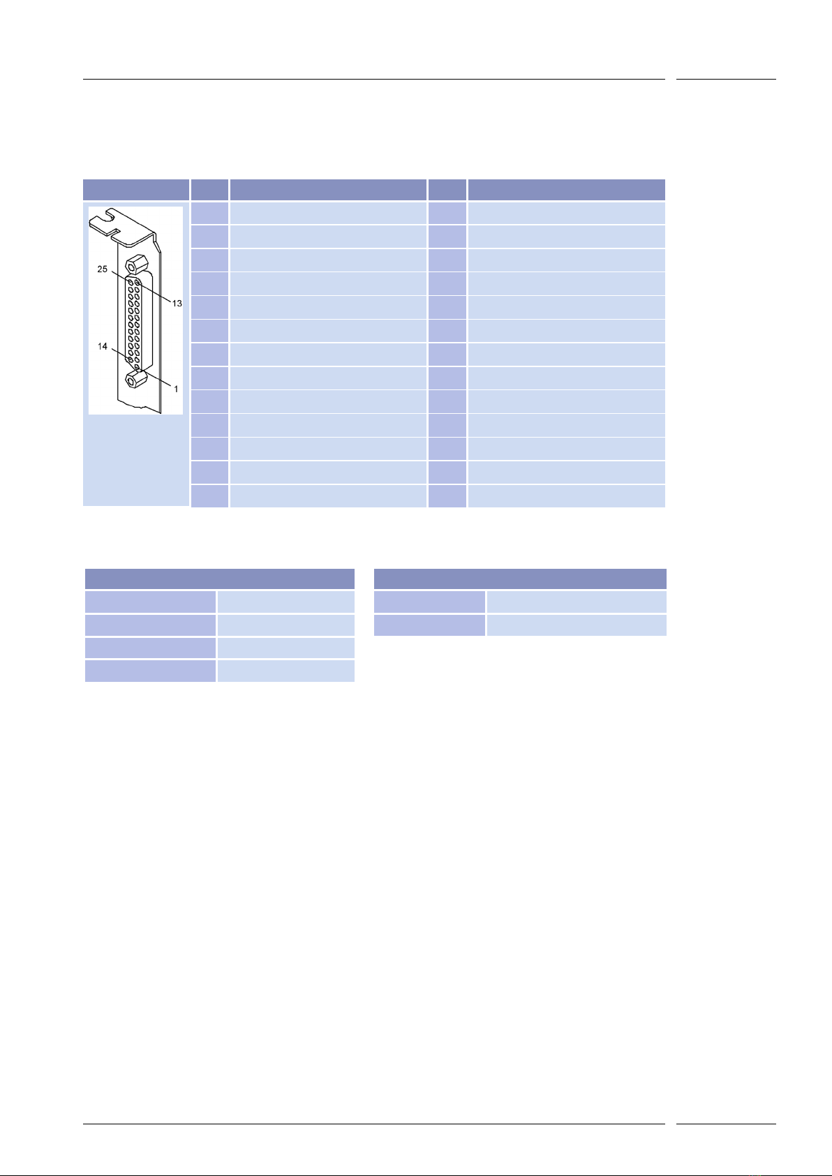
At the 25-pin D-SUB connector a RAYLASE XY(Z) scan head can be connected. All signals
are in accordance with the RAYLASE XY2-100 standard interface.
nc = not connected
Specifications
J1 PIN Signal PIN Signal
25 PIN D-SUB
1 Diff.Output- SENDCLOCK 14 Diff.Output+ SENDCLOCK
2 Diff.Output- SYNC 15 Diff.Output+ SYNC
3 Diff.Output- X-CHANNEL 16 Diff.Output+ X-CHANNEL
4 Diff.Output- Y-CHANNEL 17 Diff.Output+ Y-CHANNEL
5 Diff.Output- Z-CHANNEL 18 Diff.Output+ Z-CHANNEL
6Diff.Input- Y-Status 19 Diff.Input+ Y-Status
7Diff.Input- Z-Status 20 Diff.Input+ Z-Status
8Diff.Input- X-Status 21 Diff.Input+ X-Status
9 nc 22 nc
10 nc 23 GND
11 GND 24 GND
12 nc 25 nc
13 nc --- ---
Diff.Input-, Diff.Input+ - Diff.Output-, Diff.Output+
Input Voltage –4 to +8V Output low max. 0.5V max. 40mA
Input Threshold max. 200mV Output high min. 2.0V max. 40mA
Diff. Input Voltage max. 5V
Hysteresis typ. 70mV
Autres manuels pour SP-ICE-1 PCI/e PRO
1
Table des matières
Manuels Unité de contrôle populaires d'autres marques

Festo
Festo Compact Performance CP-FB6-E Manuel de la liste des pièces

Elo TouchSystems
Elo TouchSystems DMS-SA19P-EXTME Manuel utilisateur

JS Automation
JS Automation MPC3034A Manuel utilisateur

JAUDT
JAUDT SW GII 6406 Series Guide rapide

Spektrum
Spektrum Air Module System Manuel utilisateur

BOC Edwards
BOC Edwards Q Series Manuel utilisateur


