RAK RAK3372 Manuel utilisateur
Documentation Center
RAK3372 Quick Start Guide
This quick start guide shows how can you use the RAK3372 as a WisBlock Core module. It is a step-by-step guide
on how to prepare your hardware as well as how to set up the needed software.
There are more features and applications possible for RAK3372 WisBlock Core but this guide only demonstrates
LED Breathing and LoRaWAN OTAA example.
Following this guide successfully ensures that you have a working RAK3372 WisBlock Core.
This guide also includes instructions on how to perform firmware update.
Prerequisite
What Do You Need?
Before going through each step in the installation guide of the RAK3372 WisBlock Core Module, make sure to
prepare the necessary items listed below:
Hardware
RAK3372 WisBlock Core
Your choice of WisBlock Base
USB Cable
Li-Ion/LiPo battery (optional)
Solar charger (optional)
Software
Arduino IDE
Download and install the Arduino IDE .
⚠
WARNING
If you are using Windows 10:
Do NOT install the Arduino IDE from the Microsoft App Store. Instead, install the original Arduino IDE from
the Arduino official website. The Arduino app from the Microsoft App Store has problems using third-party
Board Support Packages.
Add RAK3172 as a supported board in Arduino IDE by updating Board Manager URLs in Preferences settings
of Arduino IDE with the JSON URL below.
After that, you can then add RAKwireless RUI STM32 Boards via Arduino board manager.
Product Configuration
Hardware Setup
https://raw.githubusercontent.com/RAKWireless/RAKwireless-Arduino-BSP-Index/main/package_rakwirel
json
Documentation Center
Your RAK3372 will not work on its own. It needs at least to be connected to a WisBlock Base together with an
antenna. You can then interface various WisBlock Modules via the available slots in the WisBlock Base. You can
also add a battery as a power source and optional solar charging. All hardware-related configurations for your
RAK3372 are discussed here.
This section covers:
RAK3372 Connection to Base Board
Assembling and Disassembling of WisBlock Modules
Antenna and Battery/Solar Connection
RAK3372 to WisBlock Base
The RAK3372 will not work without a WisBlock Base board. The WisBlock Base provides a USB connection for
programming the RAK3372. It also provides a power source and various interfaces to RAK3372 so that it can be
connected to other WisBlock Modules via different module slots.
RAKwireless offers many WisBlock Base Boards compatible with WisBlock Core. It is highly recommended to
look at these WisBlock Base boards to see what matches your requirements in terms of available module slots,
power supply options, and overall size.
⚠
WARNING
RAK3372 WB_IO3 (WisBlock IO Pin 3) is connected to PB12 of the RAK3172 module. This pin is
internally connected to a 10k resistor as mentioned on the pin definition table of the RAK3172 datasheet
. Other WisBlock modules that use this pin will have possible conflict.
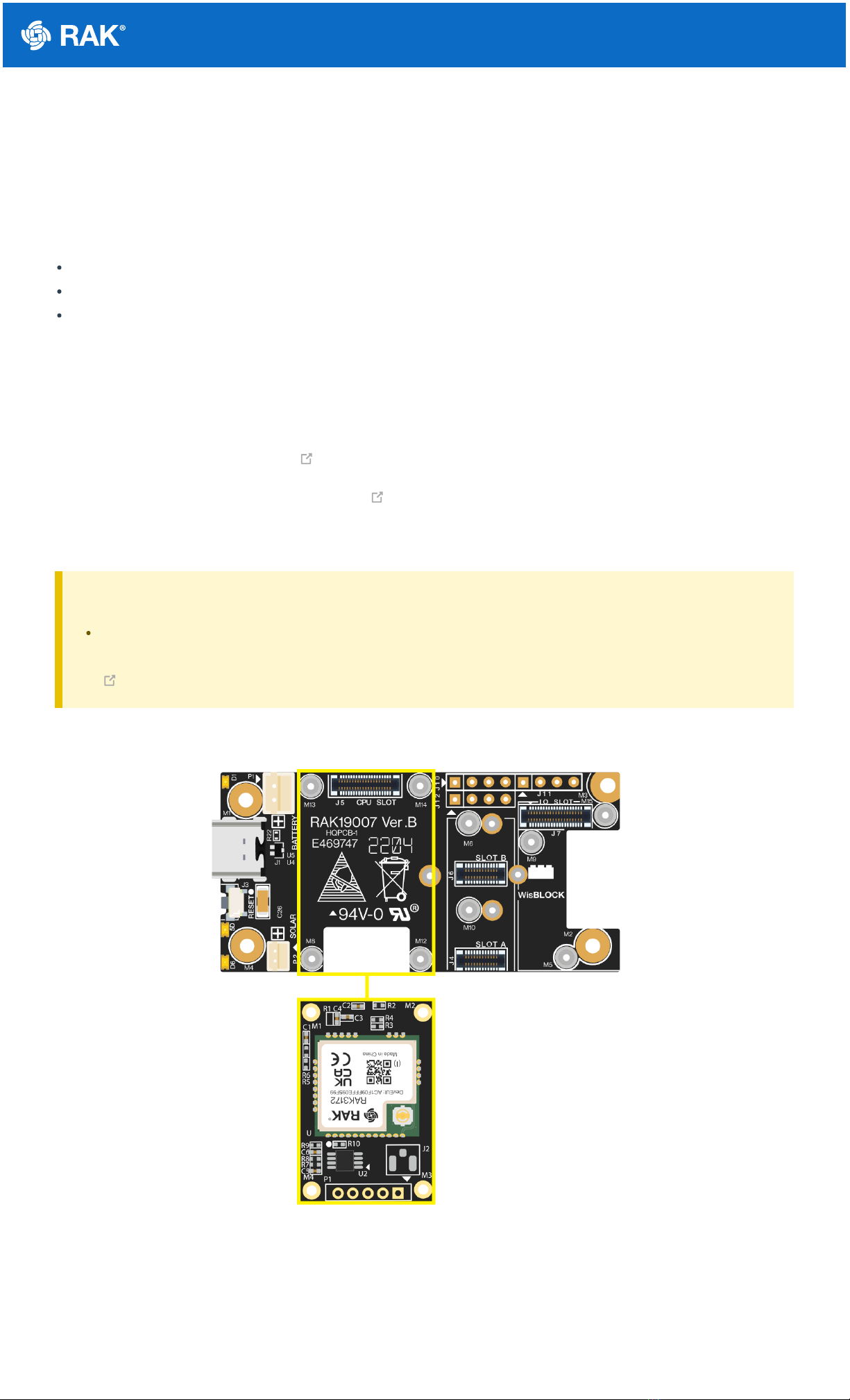
To illustrate, RAK3372 can be connected to RAK19007 WisBlock Base, as shown in Figure 1.
Figure 1: RAK3372 connection to WisBlock Base RAK19007
Some pins are exposed on RAK19007, and you can easily use them via header pins. The labels are at the back,
as shown in Figure 2.
Documentation Center
WisBlock Base exposed pins
Figure 2: WisBlock Base exposed pins
Each WisBlock Base board has its own set of header pins available for you to use. However, these header pins
are not exactly the same in each WisBlock Base. It is common to see IO pins and communication protocol pins like
I2C and UART in the WisBlock Base board. More information can be found on the official documentation of the
specific WisBlock Base you used in your project.
You can access the AT command via UART2 by default (and also possible via UART1). Firmware update is only
possible via UART2. A built-in USB-Serial converter is on the board to easily connect the RAK3372 to the USB
port of the PC.
There are useable LEDs as well in the WisBlock Base. You can control them in your code via the GREEN_LED and
BLUE_RED macro.
Assembling and Disassembling of WisBlock Modules
Assembling
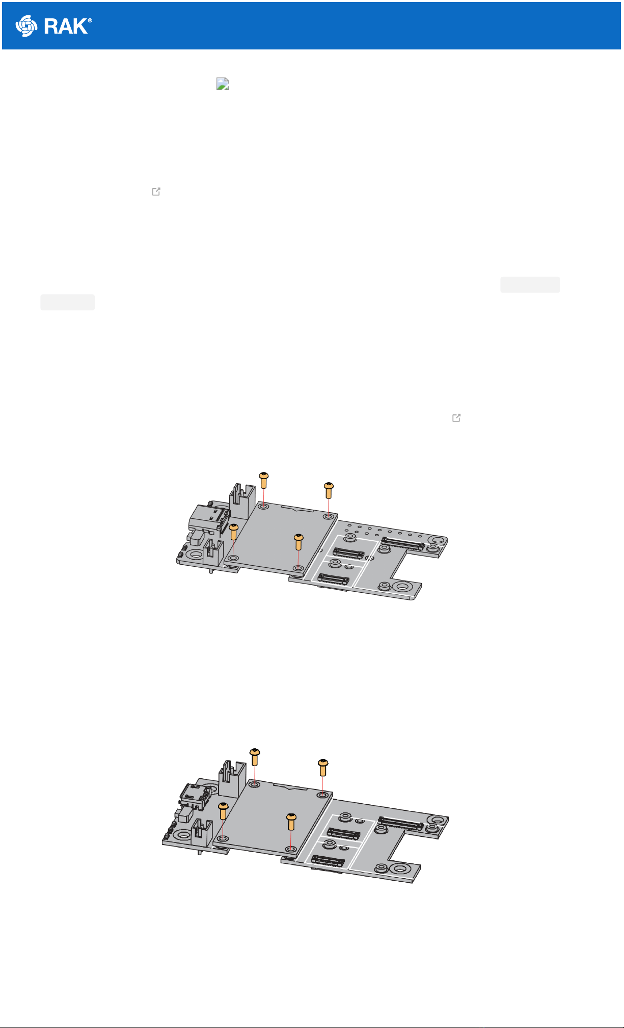
Figure 3 shows how to mount the RAK3372 module on top of a WisBlock Base board (RAK19007). Follow
carefully the procedure defined in WisBlock module assembly/disassembly instructions to secure the connection
safely. Once attached, carefully fix the module with one or more pieces of M1.2 x 3 mm screws depending on the
module.
Figure 3: RAK3372 mounting sketch
Disassembling
The procedure in disassembling any type of WisBlock module is the same.
1. First, remove the screws.
Figure 4: Removing screws from the WisBlock module
2. Once the screws are removed, check the silkscreen of the module to find the correct location where force can
be applied.

Documentation Center
Figure 5: Detaching silkscreen on the WisBlock module
3. Apply force to the module at the position of the connector, as shown in Figure 6, to detach the module from the
baseboard.
Figure 6: Applying even forces on the proper location of a WisBlock module
LoRa Antenna
Another important component of RAK3372 is the antenna.
Figure 7: LoRa antenna
You need to ensure that it is properly connected to have a good LoRa signal. Also, note that you can damage the
RF section of the chip if you power the module without an antenna connected to the IPEX connector.

Documentation Center
Figure 8: RAK3372 IPEX antenna connector
📝
NOTE
Detailed information about the RAK3372 LoRa PCB antenna can be found on the antenna datasheet .
Keep in mind that the PCB antenna is intended ideally only for prototyping and device evaluation. For
enterprise deployments, it is advisable to consider a better antenna for reliable performance.
⚠
WARNING
When using the LoRa transceiver, make sure that it is connected to an antenna. Using the transceiver
chip without an antenna can damage the system.
Make sure to fix the module with screws to ensure proper function.
Battery and Solar Connection
RAK3372 can be powered via the USB cable or Li-Ion/LiPo battery via the dedicated connectors, as shown in
Figure 9. The matching connector for the battery wires is a JST PHR-2 2 mm pitch female .
This illustration uses RAK19007 as WisBlock Base. There are other WisBlock Base boards available, and you
need to check the datasheet of the specific WisBlock Base board for the right polarity and other parameters.
⚠
WARNING
Batteries can cause harm if not handled properly.
Only 3.7-4.2 V Rechargeable LiPo batteries are supported. It is highly recommended not to use other
types of batteries with the system unless you know what you are doing.
If a non-rechargeable battery is used, it has to be unplugged first before connecting the USB cable to
the USB port of the board to configure the device. Not doing so might damage the battery or cause a
fire.
Only 5 V solar panels are supported. Do not use 12 V solar panels. It will destroy the charging unit and
eventually other electronic parts.
Make sure the battery wires match the polarity on the baseboard. Not all batteries have the same
wiring.

Documentation Center
Figure 9: WisBlock Base Battery Connection
The battery can be recharged, as well, via a small solar panel, as shown in Figure 10. The matching connector for
the solar panel wires is an JST ZHR-2 1.5 mm pitch female .
Figure 10: Solar panel connection
Specifications of the battery and solar panel can be found on the datasheet of the WisBlock Base.
Software Initial Guide
Software Setup
The default firmware of RAK3372 is based on RUI3, which allows you to develop your custom firmware to connect
sensors and other peripherals to it. To develop your custom firmware using Arduino IDE, you need first to add
RAKwireless RUI STM32 Boards in the Arduino board manager, which will be discussed in this guide. You can
then use RUI3 APIs for your intended application. You can upload the custom firmware via UART. The AT
commands of RAK3372 is still available even if you compile custom firmware via RUI3. You can send AT
commands via UART2 connection.
RAK3372 RUI3 Board Support Package in Arduino IDE
If you don't have an Arduino IDE yet, you can download it from the Arduino official website and follow the
installation procedure depending on your machine.
📝
NOTE
For Windows 10 and up users: If your Arduino IDE is installed from the Microsoft App Store, you need to
reinstall your Arduino IDE by getting it from the Arduino official website. The Arduino app from the
Microsoft App Store has problems using third-party Board Support Packages.
Once the Arduino IDE has been installed successfully, you can now configure the IDE to add the RAK3372 to its
board selection by following these steps.
1. Open Arduino IDE and go to File > Preferences.

Documentation Center
Figure 11: Arduino preferences
2. To add the RAK3372 to your Arduino Boards list, edit the Additional Board Manager URLs. Click the icon, as
shown in Figure 12.
Figure 12: Modifying Additional Board Manager URLs
3. Copy the URL below and paste it on the field, as shown in Figure 13. If there are other URLs already there, just
add them on the next line. After adding the URL, click OK.
https://raw.githubusercontent.com/RAKWireless/RAKwireless-Arduino-BSP-Index/main/package_rakwirel
json

Documentation Center
Figure 13: Add additional board manager URLs
4. Restart the Arduino IDE.
5. Open the Boards Manager from Tools Menu.
Figure 14: Opening Arduino boards manager
6. Write RAK in the search bar, as shown in Figure 15. This will show the available RAKwireless module boards
that you can add to your Arduino Board list.
7. Click on the area highlighted in blue to select RAKwireless RUI STM32 Boards. Install the latest version of the
RAKwireless RUI STM32 Boards by clicking the Install button.

Documentation Center
Figure 15: Installing RAKwireless RUI STM32 Boards
Configure RAK3372 on Boards Manager
8. Once the BSP is installed, select Tools > Boards Manager > RAKWireless RUI STM32 Modules > WisDuo
RAK3172 Evaluation Board. The RAK3372 WisBlock Core uses the RAK3172 WisDuo module, so you must
select that board as shown in Figure 16.
Figure 16: Selecting RAK3172 Module
RAK3372 COM Port on Device Manager
Connect the RAK3372 via UART and check RAK3372 COM Port using Windows Device Manager.

Documentation Center
Figure 17: Device manager ports (COM & LPT)
Compile an Example with Arduino LED Breathing
1. After completing the steps on adding your RAK3372 WisBlock Core to the Arduino IDE, you can now try to run
a simple program to test your setup. There is a built-in LED in the WisBlock Base board that you can control via
RUI3 custom firmware.
2. Launch Arduino IDE and configure WisDuo RAK3172 Evaluation Board on board selection. See Figure 16.
3. Connect the RAK3372 via UART and check RAK3372 COM Port. See Figure 17.
4. Open the Tools Menu and select a COM port. COM28 is currently used. COM port number varies depending on
the PC.
Figure 18: Select COM port
5. You can now see the serial monitor icon and click it to connect the COM port.
Table des matières
Autres manuels RAK Matériel informatique


Manuels Matériel informatique populaires d'autres marques

EMC2
EMC2 VNX Series Manuel du propriétaire

Panasonic
Panasonic DV0PM20105 Manuel utilisateur

Mitsubishi Electric
Mitsubishi Electric Q81BD-J61BT11 Manuel utilisateur

Gigabyte
Gigabyte B660M DS3H AX DDR4 Manuel utilisateur

Raidon
Raidon iT2300 Manuel utilisateur

National Instruments
National Instruments PXI-8186 Manuel utilisateur


