Phase XtalX DDQS1 Manuel utilisateur

www.phasesensors.com
XtalX DDQS1 Quartz Pressure Transducer
Mechanical User Manual

4-016 National Institute for Nanotechnology
11421 Saskatchewan Drive
Edmonton, AB, T6G 2M9
TELEPHONE: (780) 264-2659
JANUARY, 2022
©COPYRIGHT PHASE ADVANCED SENSOR SYSTEMS CORP.
XtalX DDSQ1 Quartz Pressure Transducer
Mechanical User Manual

Page 2Table of Contents
CONTENTS
SECTION
1
2
3
MECHANICAL INSTRUCTIONS
1.1 Process Fluid Fitting ..........................................................................................................................
1.2 Consumables .........................................................................................................................................
1.3 Microcap Attatchment ....................................................................................................................
XTALX DDQS1 SPECIFICATION SHEET
2.1 Specification Hightlights ...............................................................................................................
2.2 Mechanical Specifications ...........................................................................................................
2.3 Electrical Specifications .................................................................................................................
2.4 Additional Specifications ..............................................................................................................
2.5 Life Time Expectancy Note ..........................................................................................................
2.6 Frequency Response Note ..........................................................................................................
2.5 DDQS1-10000-150 Specification Drawing .........................................................................
MacOS SOFTWARE/COMMUNICATIONS
3.1 Pressure Measurment Walk Through ...................................................................................
PAGE
3
4-5
6
7
7
7
7
7
8
9
10-12

Page 3
SECTION 1
MECHANICAL INSTRUCTIONS
1.1 PROCESS FLUID FITTING
Mechanical Instructions
When removing or attaching the microcap to the pressure sensor, follow the procedures below:
Removal
1. Use a 11/16” hex wrench on the process end fitting and a spanner wrench (McMaster PN: 5472A1)
2. Turn the 11/16” wrench counter-clockwise to loosen.
3. Avoid if possible scraping angled metal surface and PTFE O-ring groove with metal parts or
process fitting threads.
4. Take care to ensure the you do not touch the membrane as it is fragile.
5. If cleaning is necessary, use Isopropanol/ acetone or other solvents to rinse the membrane
without contacting it.
6. prelace PTFE O-ring after process end fitting is removed without scratching gland surfaces.

Page 4Mechanical Instructions
Number O-Rings Size Qty. Material
1 & 3 Electronics Housing
Back-Up Ring DN-014 2 PEEK
2 & 4 E-H O-Ring DN-014 2 FFKM
5Process-Side O-Ring M14 x 1mm 1 PTFE
*Note: The O-rings in the above table are not compatible with acetone.
1.2 CONSUMABLES
The following 0-rings may need to be replaced during the life of the sensor:

Page 5Mechanical Instructions
The placement of the O-ring is shown below:
21
Figure 1-1. Placement of O-rings
43 5

Page 6Mechanical Instructions
1.3 MICROCAP ATTATCHMENT
Feedthrough Spanner
11/16” Hex Wrench Membrane
*DO NOT TOUCH*
Figure 1-2. Microcap Attatchment
PTFE
1. Heat PTFE O-ring to 100°C for easier installation of O-ring.
2. Take care to ensure the you do not touch the membrane as it is fragile.
3. Engage the threads by hand while gently pushing the process end fitting.
4. Use a 11/16” hex wrench on the microcap and a spanner wrench on the feedthrough.
5. Turn the 11/16” wrench clockwise. Hand tighten process fitting to feedthrough end.
6. Torque to 40 N•m, do not over torque as this may damage metal to metal seal.
7. Gap between lip of process fitting and feedthrough should be approximately 0.02”.

2.1 SPECIFICATION HIGHLIGHTS
CALIBRATED RANGE .................................... ATM to 10, 000 PSI (1 to 690 BAR)
CALIBRATED TEMPERATURE RANGE .............................................. 20° TO 150°C
PRESSURE ACCURACY ..................................................................................... 0.02 %F.S.
DRIFT @ MAX TEMPERATURE & PRESSURE ............................ 0.1%F.S./YEAR
TEMPERATURE ACCURACY .................................................................................... 0.01°C
DRIFT @ MAX TEMPERATURE & PRESSURE ................................ 0.01°C/YEAR
2.2 MECHANICAL SPECIFICATIONS
WEIGHT: 325 GRAMS
HEIGHT: 152 mm (6”)
MAXIMUM WIDTH: 25 mm (0.75”)
PROOF PRESSURE: 103MPA (15,000PSI)
HOUSING MATERIAL: INCONEL 718
2.3 ELECTRICAL SPECIFICATIONS
MAXIMUM VOLTAGE RATINGS ............................................................... -0.3 TO 13.5V
DC VOLTAGE SUPPLY RANGE ....................................................................... 2.9 TO 12V
DC CURRENT DRAW @ 25°C ............................................................................. 29.2 mA
CURRENT DRAW @ F.S. TEMP ......................................................................... 37.5 mA
OUTPUT ............................................................................................................... TTL-232R-2V7
BAUD RATE ........................................................................................................................ 57600
ESD ............................................................................................................................................ ±2kV
STARTUP TMIE & SETTLE TIME .......................................................................... 230 ms
Page 7Specification Sheet
SECTION 2
XTALX DDQS1 SPECIFICATION SHEET
MAX CURRENT CONSUMPTION ........................................................................ 40 mA
LOW POWER STATE CURRENT DRAW 1s SAMPLE @ 25°C ......... 1.212 mA
LOW POWER STATE CURRENT DRAW 1s SAMPLE @ F.S TEMP.. 2.9 mA
LOW POWER STATE CURRENT DRAW 9s SAMPLE @ 25°C .......... 400 uA
LOW POWER STATE CURRENT DRAW 9s SAMPLE @ F.S TEMP 700uA
2.4 ADDITIONAL SPECIFICATIONS
STORAGE TEMPERATURE ........................................................................ -65° to 150°C
ACHIEVABLE RESOLUTION ............................................................................... 0.002psi
REPEATABILITY ....................................................................................................... 0.05% F.S.
NOMINAL SENSITIVITY ............................................................................................ 3psi/Hz
RESPONSE TIME ................................................................................................................... 0.1s
GRAVITATIONAL EFFECTS ........................................................................ NEGLIGIBLE
ORIENTATIONAL EFFECTS ....................................................................... NEGLIGIBLE
ACCELERATION SENSITIVITY ................................................................. NEGLIGIBLE
STARTUP TIME 25°C ............................................................................................. 130 ms
PEAK INRUSH CURRENT 25°C .................................................................. 37.12 mA
STARTUP TIME F.S. TEMP ................................................................................. 150 ms
PEAK INRUSH CURRENT F.S. TEM ............................................................ 40 mA
AVERAGE LIFETIME EXPECTANCY 150°C .......................................... 2 YEARS
AVERAGE LIFETIME EXPECTANCY 175°C .................................... 6 MONTHS
AVERAGE LIFETIME EXPECTANCY 210°C ........................................... 30 DAYS

2.5 LIFE TIME EXPECTANTCY NOTE:
Operating at extreme temperatures can and will dramatically reduce life expectancy. The expected
lifetimes above were observed in a dry environment where both the electronics and pressure fittings
were subject to atmosphere. XS-HTI-4 is not rated for operation beyond 175°C and 10000psi; accuracy
and quality will not be guaranteed.
2.6 FREQUENCY RESPONSE NOTE:
An increase in pressure applied to the sensor will result in a decrease of the pressure oscillator
frequency (approximately 3 PSI/Hz). Transient temperature effects will influence the pressure oscillator
frequency. Therefore, the temperature oscillator is used in tandem. An increase in temperature of
the sensor will result in an increase of the temperature oscillator frequency (approximately 0.1°C/Hz).
Pressure readings during temperature stability will result in optimal performance.
Page 8Specification Sheet
Page 9Specification Sheet
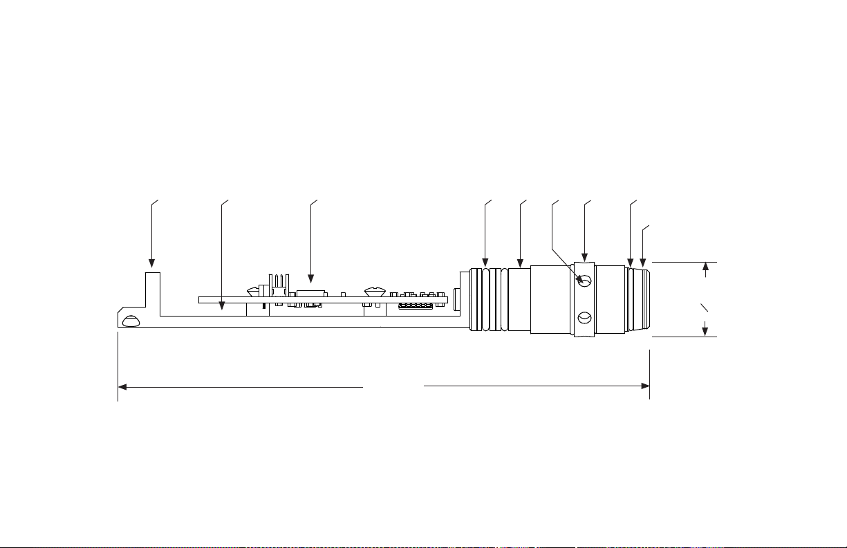
Figure 2-1. DDQS1 Pressure Transducer Specification Drawing
2.7 DDQS1-10000-150 SPECIFICATION DRAWINGS
5.32”
O.75”
Customizable connection to
memory board chassis
Aluminum circuit chassis with
shock-absorbing standoffs
High accuracy digital frequency
counting circuit board
Electronics housing seal
option 1: double o-ring/backup
Inconel 718 high pressure
feedthrough
Pressure and temperature
crystal housing
Metal seal surface
with backup o-ring
Process uid isolation
membrane
Spanner holes for 1/8” pins
Table des matières
Manuels Transducteur populaires d'autres marques


Mianyang Weibo Electronic
Mianyang Weibo Electronic WB Series Manuel utilisateur

ProMinent
ProMinent Dulcometer DMT Manuel utilisateur

MKS
MKS MicroPirani 925 Series Comment utiliser

WIKA
WIKA WU-20 Manuel utilisateur

Alcatel Vacuum Technology
Alcatel Vacuum Technology BARATRON 622A Manuel utilisateur

Camille Bauer
Camille Bauer SIRAX CH-5610 Manuel utilisateur


