OSS OSS-CPCIE3-3U-CR-4-M.2 Manuel utilisateur

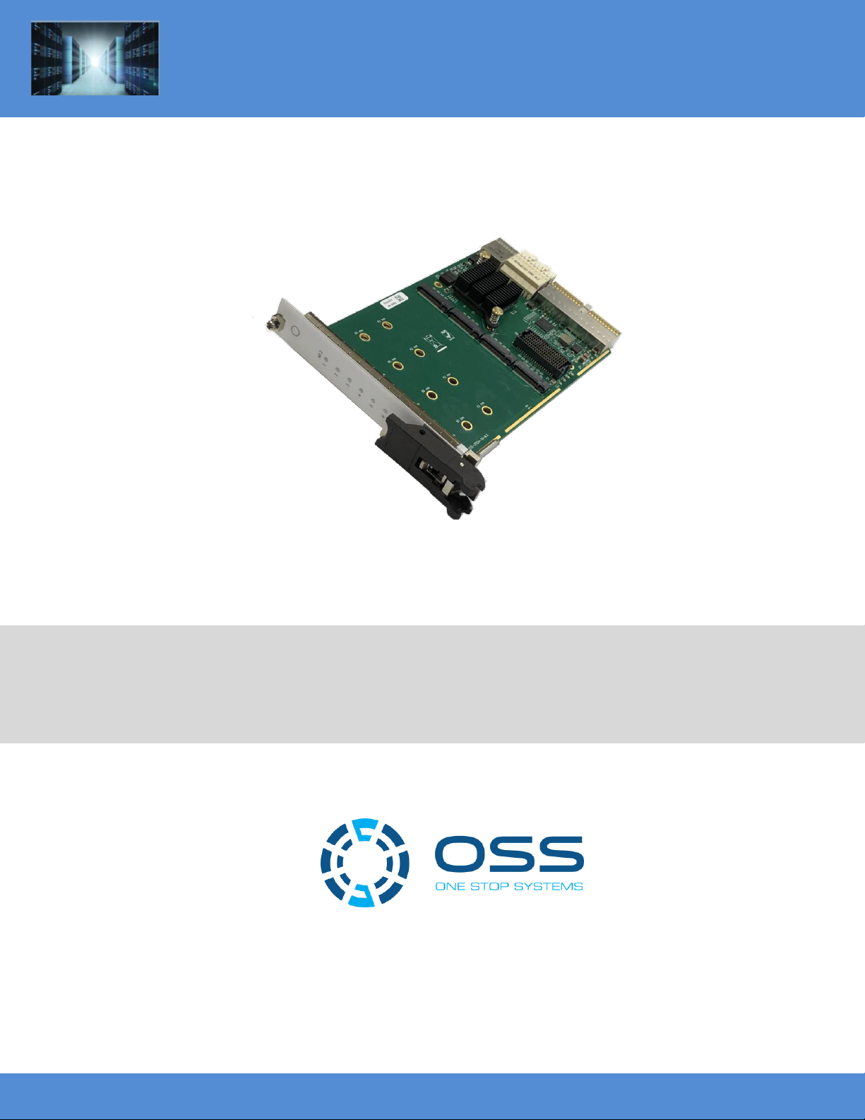
CPCIe M.2 Flash Storage Module
Model: OSS-CPCIe3-3U-CR-4-M.2 / OSS-CPCIe3-3U-CR-8-M.2
www.onestopsystems.com
CPCIe M.2 Flash Storage Module
SKU: OSS-CPCIe3-3U-CR-4-M.2
OSS-CPCIe3-3U-CR-8-M.2

One Stop Systems
OSS-CPCIe3-3U-CR-X | 2
Table of Contents
Preface 4
Advisories 4
Safety Instructions 5
1 Introduction 7
1.1 Specifications 7
1.2 478 Block Diagram 8
1.3 M.2 Interface 9
1.4 Optional Mezzanine board 9
1.4 Board Dimensions 10
1.4.1 OSS-478 (OSS-CPCIe-3U-M.2) 10
1.4.2 OSS-481 (OSS-MEZZ-M.2) 10
1.5 478 and 481 Combined 11
1.6 PCIe link LEDs 11
1.7 General Features 11
1.8 PLX 8748 (48-lane) PCIe Switch 12
1.9 Parts of OSS-478 board 12
2 Hardware & Software Requirements 13
2.1 Hardware 13
2.2 Software 13
2.3 Tools Required for Installation 13
3 Installation Procedures 14
3.1 Installation on CPCIe Host unit 14
3.2 Prepare the 0SS-478 board 14
3.3 Mount the M.2 CARD 14
3.4 Install the CPCIe M.2 Flash Storage Module 17
3.5 Connect Power and Power UP 17
3.6 Verify Bracket LEDs 17
4 Software Installation 18
5 Identify / Verify the M.2 device 19
5.1 Windows 10 19
5.2 Windows 8 21
5.3 Windows Vista and 7 22
5.4 Disk Management in Windows Server 2012? 23
5.5 Managing the M.2 devices 25
6 Read & Write Performance 26
6.1 Sequential Write Performance 26
6.2 Sequential Read Performance 26
7 How to Get More Help 27

One Stop Systems
OSS-CPCIe3-3U-CR-X | 4
Preface
Advisories
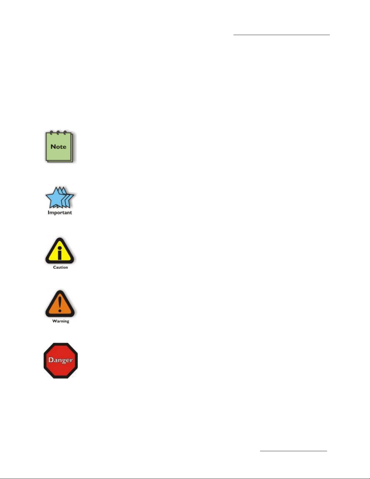
Five types of advisories are used throughout this manual to provide helpful information, or to alert you to the potential for hardware damage
or personal injury.
NOTE
Used to amplify or explain a comment related to procedural steps or text.
IMPORTANT
Used to indicate an important piece of information or special “tip” to help you
CAUTION
Used to indicate and prevent the following procedure or step from causing damage to the equipment.
WARNING
Used to indicate and prevent the following step from causing injury.
DANGER or STOP
Used to indicate and prevent the following step from causing serious injury or significant data loss
Disclaimer: We have attempted to identify most situations that may pose a danger, warning, or caution condition in this manual. However, the
company does not claim to have covered all situations that might require the use of a Caution, Warning, or Danger indicator.

One Stop Systems
OSS-CPCIe3-3U-CR-X | 5
Safety Instructions
Always use caution when servicing any electrical component. Before handling the expansion chassis, read the following instructions and safety
guidelines to prevent damage to the product and to ensure your own personal safety. Refer to the “Advisories” section for advisory
conventions used in this manual, including the distinction between Danger, Warning, Caution, Important, and Note.
Always use caution when handling/operating the computer. Only qualified, experienced, authorized electronics personnel should
access the interior of the computer and expansion chassis per UL and IEC 60950-1
The power supplies produce high voltages and energy hazards, which can cause bodily harm.
Use extreme caution when installing or removing components. Refer to the installation instructions in this manual for precautions
and procedures. If you have any questions, please contact Technical Support.
WARNING
Never modify or remove the radio frequency interference shielding from your workstation or expansion unit. To do so may
cause your installation to produce emissions that could interfere with other electronic equipment in the area of your
system.
When Working Inside a Computer
1. Before taking covers off a computer, perform the following steps:
2. Turn off the computer and any peripheral devices.
3. Disconnect the computer and peripheral power cords from their AC outlets or inlets in order to prevent electric shock or system
board damage.
In addition, take note of these safety guidelines when appropriate:
To help avoid possible damage to systems boards, wait five seconds after turning off the computer before removing a component,
removing a system board, or disconnecting a peripheral device from the computer.
When you disconnect a cable, pull on its connector or on its strain-relief loop, not on the cable itself. Some cables have a connector
with locking tabs. If you are disconnecting this type of cable, press in on the locking tabs before disconnecting the cable. As you pull
connectors apart, keep them evenly aligned to avoid bending any connector pins. Also, before connecting a cable, make sure both
connectors are correctly oriented and aligned.
CAUTION
Do not attempt to service the system yourself except as explained in this manual. Follow installation
instructions closely.

One Stop Systems
OSS-CPCIe3-3U-CR-X | 6
Protecting Against Electrostatic Discharge
Electrostatic Discharge (ESD) Warning
Electrostatic Discharge (ESD) is the enemy of semiconductor devices. You should always take precautions to eliminate any
electrostatic charge from your body and clothing before touching any semiconductor device or card by using an
electrostatic wrist strap and/or rubber mat.
Static electricity can harm system boards. Perform service at an ESD workstation and follow proper ESD procedures to reduce the risk of
damage to components. We strongly encourage you to follow proper ESD procedures, which can include wrist straps and smocks, when
servicing equipment.
You can also take the following steps to prevent damage from electrostatic discharge (ESD):
When unpacking a static-sensitive component from its shipping carton, do not remove the component’s anti-static packaging
material until you are ready to install the component in a computer. Just before unwrapping the anti-static packaging, be sure you
are at an ESD workstation or are grounded.
When transporting a sensitive component, first place it in an anti-static container or packaging.
Handle all sensitive components at an ESD workstation. If possible, use anti-static floor pads and workbench pads.
Handle components and boards with care. Do not touch the components or contacts on a board. Hold a board by its edges or by its
metal mounting bracket.

One Stop Systems
OSS-CPCIe3-3U-CR-X | 7
1 Introduction
The CPCIe 3U M.2 Flash Memory Board supports up to 32TB of flash in a single PXIe or CPCIe Type 2/Hybrid slot. The backplane connection
supports up to PCIe 3.0 x8 to the M.2 drives for up to 64Gb/s bandwidth to the M.2 drives. Provides up to 32TB of storage in the card when
using a mezzanine and 4TB modules.
Part#:
OSS-478
OSS-481
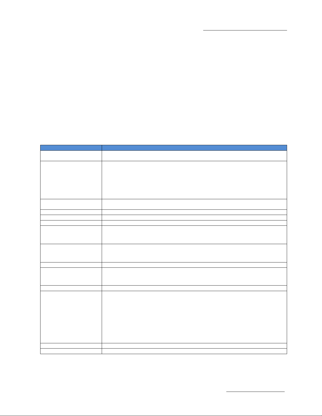
1.1 Specifications
Item
Description
Form Factor
3U CPCIe/PXIe Type 2
Single slot order time option (not field upgradeable)
Dimensions
3.94 x 6.3” (100 x 160 mm) (H x L)
Single Slot 4HP, 0.8" width (OSS-478)
Single Slot 8HP, 0.8" width (OSS-478 + OSS-481 mezzanine)
Weight: 3 lb
Bandwidth / Backplane
Interface
PCIe x8 Gen3 (64Gb/s)
M.2 Interface
Four or Eight x4 Gen3 (32Gb/s) to each M.2
M.2 Modules
80mm up to 4TB each
RAID Configurations
Supports JBOF and Software RAID 0, 1, 5, 10 and 50
Front Panel Indicators
1 Power-on LED (green)
4 or 8 M.2 link status LEDs (green)
Backplane Connectors
XJ3 and XJ4 connectors
Optional J1 connector for use in hybrid slots (OEM option)
Power Consumption
30W max
Temperature Range
Operating: 0°to 55°C
Non-operating: -40°to 85°C
Relative Humidity
10 to 90% non-condensing
Agency/Compliances
Designed to Meet:
FCC Part 15 Subpart B, Class A
CE
RoHS
EN55022, Class A
EN55024
EN300386-2
Operating System
Windows 10, Windows Server 2012 R2

One Stop Systems
OSS-CPCIe3-3U-CR-X | 8
1.2 478 Block Diagram
OSS-478 (OSS-CPCIe-3U-M.2)

One Stop Systems
OSS-CPCIe3-3U-CR-X | 9
1.3 M.2 Interface
Since M.2 allows for direct communication over PCIe at up to 4 lanes without a controller chip, a PCIe switch chip is used on the M.2 mezzanine
board to provide maximum lanes to each M.2 module
1.4 Optional Mezzanine board
OSS-481 (OSS-MEZZ-M.2)

One Stop Systems
OSS-CPCIe3-3U-CR-X | 10
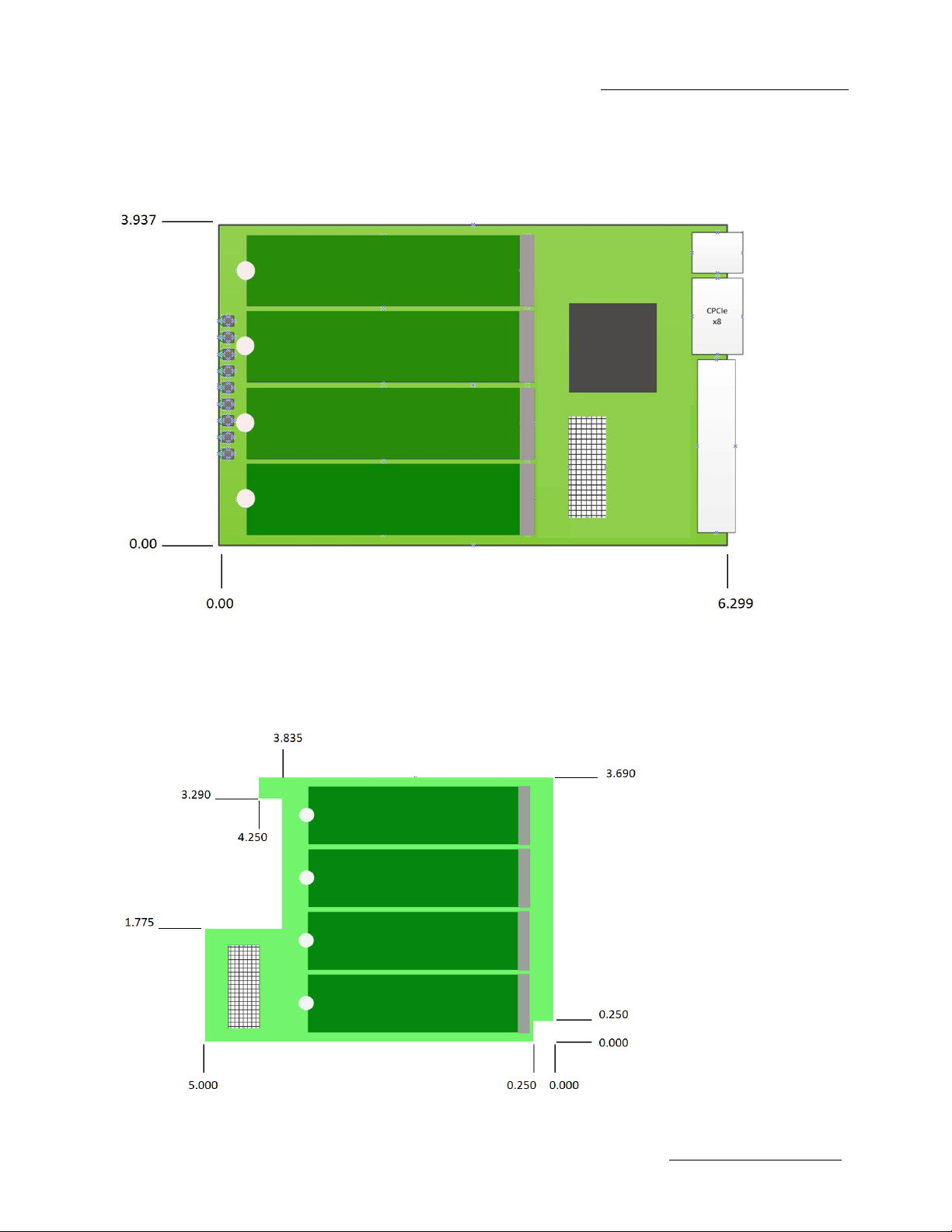
1.4 Board Dimensions
1.4.1 OSS-478 (OSS-CPCIe-3U-M.2)
1.4.2 OSS-481 (OSS-MEZZ-M.2)
Ce manuel convient aux modèles suivants
1
Table des matières
Manuels Unité de contrôle populaires d'autres marques

Festo
Festo Compact Performance CP-FB6-E Manuel de la liste des pièces

Elo TouchSystems
Elo TouchSystems DMS-SA19P-EXTME Manuel utilisateur

JS Automation
JS Automation MPC3034A Manuel utilisateur

JAUDT
JAUDT SW GII 6406 Series Guide rapide

Spektrum
Spektrum Air Module System Manuel utilisateur

BOC Edwards
BOC Edwards Q Series Manuel utilisateur