~ 8 ~
NOVATEK-ELECTRO PEF-321АВР
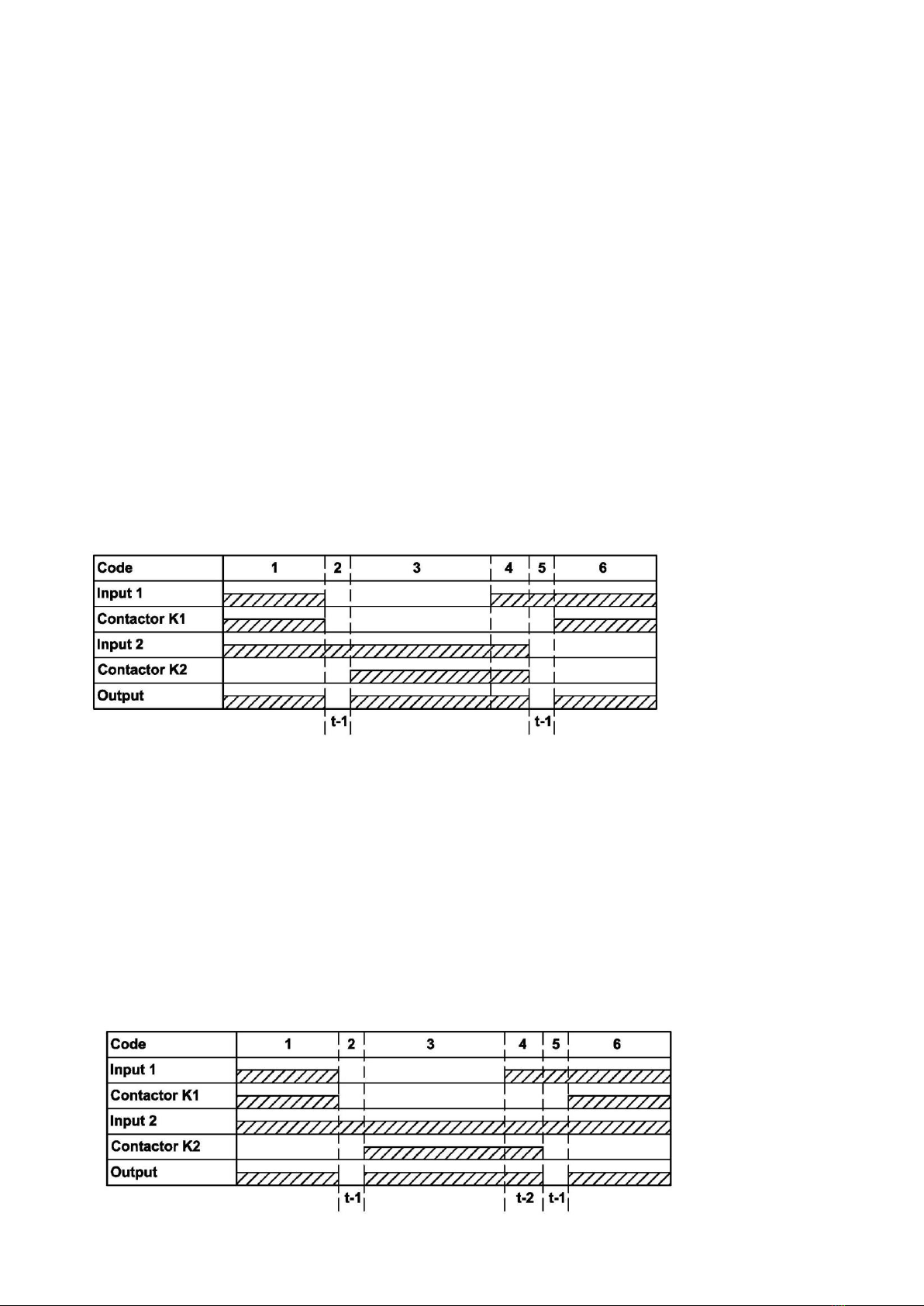
Detailed description of Figure 5:
1 –normal voltages are present at inputs 1, 2. Device 321АВР connected the load to input 1 by contactor
K1.
2 –at input 1, the voltage went beyond the limits set by the user (a failure occurred). The device
disconnects the load from input 1 by contactor K1 and counts the transition time to input 2 («»,
table 5).
3 –after the completion of the «», countdown, the device connects the load to input 2 by contactor K2.
4 –Some voltage appeared at input 1. Device 321АВР counts the time of return to the priority input («»,
table 5).
5 –the device disconnects the load from input 2 by contactor K2 and counts the transition time to another
input («», table 5).
6 –the device connects the load to input 1 by contactor K1.
6.2.1.3 To work with a three-phase generator, it must be connected to input 2 (terminals 30–33) and select
the appropriate mode of operation with a three-phase generator –«» («», table 5). The trigger signal for the
generator is generated by the device in the event that a failure occurs at input 1. The start and stop signal of the
generator is shaped by the internal relay of the device, the contacts of which go to terminals 20, 21, 22 (20 - 21 -
normally open contact, 21 - 22 normally closed contact).
Fig. 6 –Diagrams of works
with a generator at input 2
A detailed description of work with a generator, in accordance with Fig. 6:
1 –Input 1 has a normal voltage. Device 321 АВР connected the load to input 1 by Contactor K1. The LED
«»does not light.
2 –At input 1, voltage went beyond the limits set by the user (a failure occurred). The device disconnects
the load from input 1 by contactor K1 and counts the transition time to the secondary input («»,
table 5).
3 –After completion of the «», 321АВР time countdown, device 321АВР closes terminals 20 - 21 (sends
a signal to start the generator). The time for starting and warming up of the generator is counted
(«», table 5). A test check is made for absence of voltage at the load (terminals 34 - 36) and for
absence of failures at input 2. The LED «» flashes.
4 –The device connects the load to input 2 by contactor K2. The LED «»lights up.
5 –Some voltage appeared at input 1. The device counts the time of return to the priority input («»,
table 5).
6 –After completion of the «» countdown, the device disconnects the load from input 2 by the contactor
K2. A test check is made for absence of voltage at the load (terminals 34 36) and absence of failures at
input 1. The device will count the time «»and «» (table 5). The LED «»flashes.
7 –After completion of time «»countdown, the device will connect the load to input 1 by contactor K1.
8 –After completion of the «»countdown, the device will open terminals 20 - 21 (it sends a signal to turn
off the generator). The LED «» goes off.
6.2.1.4 Battery connection
The battery is connected to terminals 39 and 40, as shown in Figure 3.
The battery is charged in the buffer mode with current of not more than 60 mA. It is not recommended to use
a battery with a capacity of more than 2 Ah because of the low charge current.
Attention! Devices connected in parallel to the battery affect its charge.
If there is voltage of 100 V, at least at one of the phases of any input, the device is powered by this voltage.
Otherwise, 321 АВР is powered by a battery with current of not more than 100 mA. If the battery is discharged to
11.5 V, then 321АВР will disconnect the battery from the circuit and it will stop working. The next time the device