naturaled Bollard Manuel utilisateur

WET
LED
MADE IN CHINA
LED 5.5“ Bollard
LED 5.5” Bollard Accessories
Flat Head Round Head
φ10.5*φ20*2mm Flat washer (3 pcs)
φ10*φ16*2.7mm Spring washer (3 pcs)
M5*10 Screw (3 pcs)
Sealing ring (1 pc)
M10 Hexagon nut (3 pcs)
Buried Type-L screw (3 pcs)
Screw fixed plate (1 pc)
or
Installation Guide
V1.0
Page 1-7
120-277
Flat head installed as example.
Figure 1
Figure 2
Figure 3
Figure 4
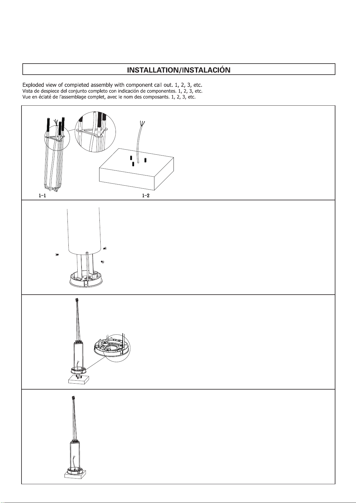
Ensure power is o before installation. Fix the screw position with
type-L screws xed plate and ll with cement.
As shown in gure 1-2.
1.
Installation Guide
V1.0
Page 2-7
LED 5.5“ Bollard
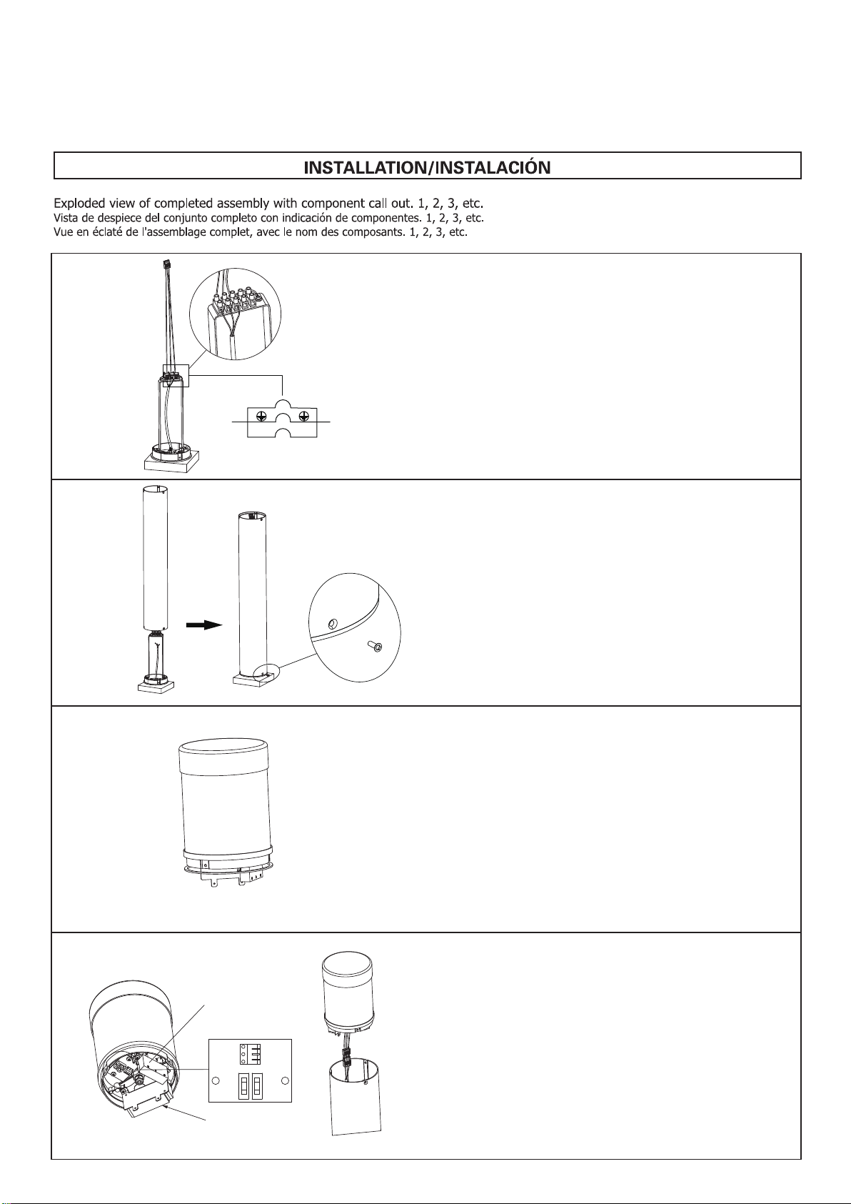
Place the at washer and spring washer on the three type-L screws
and tighten with M10 hexagon nuts of M10*8.
4.
Remove M5*10 screws and reserve them, take the base from body
of xture.
2.
Pass the input wire through the base and install the base to the
buried type-L screws.
3.
Asegúrese de que la energía esté apagada antes de la
instalación. Fijar la posición del tornillo con tornillos tipo L placa
fija y rellenar con cemento. Como se muestra en la figura 1-2.
Assurez-vous que l'alimentation est coupée avant l'installation.
Fixez la position de la vis avec des vis de type L plaque fixe et
remplissez de ciment. Comme le montre la figure 1-2.
Retire los tornillos M5*10 y resérvelos, saque la base del cuerpo
de la pilona.
Retirez les vis M5 * 10 et réservez-les, retirez la base du corps de
la borne.
Pase el cable de entrada a través de la base e instale la base con
los tornillos tipo L enterrados.
Passez le câble d'entrée à travers la base et installez la base avec
les vis enterrées de type L.
Empuje la arandela plana y la arandela elástica a través de los
tres tornillos tipo L y apriete con tuercas hexagonales M10.
Poussez la rondelle plate et la rondelle élastique à travers les
trois vis de type L et serrez avec des écrous hexagonaux M10.
Flat head installed as example.
Figure 5
Figure 6
Figure 7
Figure 8
Installation Guide
V1.0
Page 3-7
LED 5.5“ Bollard
Connect the cable to the wiring terminal according to wiring
diagram.
5.
Input Output
N
L
N
L
Fix the body with the base by reserved M5*10 screws in Figure 2.
6.
Take the head from box. Place the sealing ring under the transition
end cover.
7.
Conecte el cable al terminal de cableado de acuerdo con el
diagrama de cableado.
Connectez le câble à la borne de câblage conformément au
schéma de câblage.
Fije el cuerpo con la base mediante los tornillos M5*10
reservados en la Figura 2.
Fixez le corps avec la base par les vis M5*10 réservées à la
Figure 2.
Saca la cabeza de la caja. Coloque el anillo de sellado debajo de
la cubierta del extremo de transición.
Prenez la tête de la boîte. Placez la bague d'étanchéité sous le
couvercle d'extrémité de transition.
Ajuste la potencia y el interruptor CCT según sus requisitos,
inserte el enchufe macho y hembra.
Configuración predeterminada: Vatios: 18SW (18 W)/CCT: 5000K
Ajustez la puissance et le commutateur CCT en fonction de vos
besoins, insérez la prise mâle et femelle.
Réglage par défaut : Watts : 18SW (18 W)/CCT : 5000K
Adjust wattage and CCT switch according to your requirement,
insert male and female plug.
Default Setting: Watts:18SW(18W)/CCT:5000K
8.
Driver
SPD09P-10R

Spray expanding foam, used to fill and seal the base of the bollard body.
Below instructions should be followed to minimize condensation of moisture on the inside of the lens
:
Installation Guide
V1.0
Page 4-7
Figure 1
Figure 2 Fill the bottom of the bollard with approximately 5 inches of spray
expanding foam, ensuring the foam makes complete contact
around the conduitand the inside of the bollard body.
2.
Make certain power is switched OFF before starting installation.
Remove the base from the bollard and retain the set screws to use
when reinstalling the bollard body.
1.
LED 5.5“ Bollard
Flat head installed as example.
Figure 9
Place the head in the body and lock with M5*10 screws.
Complete the bollard installation following all NEC and applicable
local Codes and Ordinances.
9.
Coloque la cabeza en el cuerpo y bloquéela con tornillos M5*10.
Complete la instalación del bolardo siguiendo todos los códigos y
ordenanzas locales aplicables y NEC.
Placez la tête dans le corps et verrouillez avec des vis M5*10.
Terminez l'installation de la borne en suivant tous les codes et
ordonnances NEC et locaux applicables.
Asegúrese de que la alimentación esté APAGADA antes de
comenzar la instalación. Retire la base del bolardo y conserve los
tornillos de fijación para utilizarlos cuando vuelva a instalar el
cuerpo del bolardo.
Assurez-vous que l'alimentation est coupée avant de commenc-
er l'installation. Retirez la base de la borne et conservez les vis
de réglage à utiliser lors de la réinstallation du corps de la
borne.
Llene la parte inferior del bolardo con aproximadamente 5
pulgadas de espuma expansiva en aerosol, asegurándose de que
la espuma haga contacto completo alrededor del conducto y el
interior del cuerpo del bolardo.
Remplissez le bas de la borne avec environ 5 pouces de mousse
expansible par pulvérisation, en veillant à ce que la mousse soit
en contact complet autour du conduit et à l'intérieur du corps de
la borne.

Spray expanding foam, used to fill and seal the base of the bollard body.
Below instructions should be followed to minimize condensation of moisture on the inside of the lens
:
Installation Guide
V1.0
Page 5-7
LED 5.5“ Bollard
Allow time for foam to expand, then visually inspect to conrm the
foam does not contain gaps between the foam and the conduit, or
the foam and the inside of the bollard body.
3.
Complete the bollard installation following all NEC and applicable
local Codes and Ordinances.
4.
Figure 3
Figure 4
Figure 1
TYPE 3 PLATE INSTALLATION
Remove M5*10 screws, take the bollard head from body.
1.
Flat head installed as example.
Permita que la espuma se expanda, luego inspeccione
visualmente para confirmar que la espuma no tenga espacios
entre la espuma y el conducto, o entre la espuma y el interior del
cuerpo del bolardo.
Laissez le temps à la mousse de se dilater, puis inspectez
visuellement pour confirmer que la mousse ne contient pas
d'espace entre la mousse et le conduit, ou entre la mousse et
l'intérieur du corps de la borne.
Complete la instalación del bolardo siguiendo todos los códigos y
ordenanzas locales aplicables y NEC.
Terminez l'installation de la borne en suivant tous les codes et
ordonnances NEC et locaux applicables.
Retire los tornillos M5*10, saque la cabeza del bolardo del cuerpo.
Retirez les vis M5 * 10, retirez la tête de la borne du corps.

Installation Guide
V1.0
Page 6-7
Figure 2
Figure 3
LED 5.5“ Bollard
TYPE 3 PLATE INSTALLATION
Figure 4
Figure 5
Pull out the top cover of bollard.
3.
Insert Type 3 plate into the xture head.
4.
Fix the M12 nut and waterproof connector of the bollard head.
5.
Flat head installed as example.
Retire el conector impermeable y la tuerca M12 en la parte inferior
de la cabeza del bolardo.
Retirez le connecteur étanche et l'écrou M12 au bas de la tête de
la borne.
Saque la cubierta superior del bolardo.
Retirez le couvercle supérieur de la borne.
Inserte la placaTipo 3 en el cabezal de la luminaria.
Insérez la plaque de type 3 dans la tête du luminaire.
Fijar la tuerca M12 y el conector estanco de la cabeza de la pilona.
Fixez l'écrou M12 et le connecteur étanche de la tête de borne.
Remove waterproof connector and M12 nut at the bottom of the
bollard head.
2.
Waterproof
connector
M12 Nut
SPD09P-10R
Driver
Sealing gasket
Sealing gasket
Waterproof
connector
M12 Nut
SPD09P-10R
Driver
Sealing gasket
Sealing gasket

TYPE 3 PLATE INSTALLATION
Flat head installed as example.
Figure 6
Place the head in the body and lock with M5*10 screws.
Complete the bollard installation following all NEC and applicable
local Codes and Ordinances.
6.
Coloque la cabeza en el cuerpo y bloquéela con tornillos M5*10.
Complete la instalación del bolardo siguiendo todos los códigos y
ordenanzas locales aplicables y NEC.
Placez la tête dans le corps et verrouillez avec des vis M5*10.
Terminez l'installation de la borne en suivant tous les codes et
ordonnances NEC et locaux applicables.
M5×3
23.527.5
15.9
24
2.5
R5.5
5R7
13
R6.5
R6
R53.63
R53.63
14.42
R9
R5.52
Ø10
M4×2
Ø140
Ø5
M4×2
Ø5
Ø25
Installation Guide
V1.0
Page 7-7
LED 5.5“ Bollard
BOLT CIRCL E ORI E NTATION
Table des matières
Autres manuels naturaled Éclairage extérieur

Manuels Éclairage extérieur populaires d'autres marques


Lindby
Lindby 9949029 Manuel utilisateur

HEPER
HEPER DOGO Side LW6048.585-US Instructions d'installation et d'utilisation

HEPER
HEPER LW8034.003-US Instructions d'installation et d'utilisation

Maretti
Maretti VIBE S 14.6080.04.A Manuel utilisateur

BEGA
BEGA 84 253 Manuel

HEPER
HEPER MINIMO Instructions d'installation et d'utilisation

LIGMAN
LIGMAN BAMBOO 3 Manuel utilisateur

Maretti
Maretti TUBE CUBE WALL 14.4998.04 Manuel utilisateur

Maxim Lighting
Maxim Lighting Carriage House VX 40428WGOB Manuel utilisateur

urban ambiance
urban ambiance UQL1273 Manuel utilisateur

TotalPond
TotalPond 52238 Manuel utilisateur

Donner & Blitzen
Donner & Blitzen 0-02661479-2 Manuel utilisateur