Monorail NT5100G-16M BD Manuel utilisateur

SERVICE & MAINTENANCE
MANUAL
October 1997

The information in this document is
subject to change without notice.
Monorail Inc. makes no warranty of any
kind with regard to this material.
Monorail shall not be liable for technical
or editorial errors or omissions contained
herein; nor for incidental or consequential
damages resulting from the furnishing,
performance, or use of this material.
This document contains information that is
protected by copyright. No part of this
document may be photocopied,
reproduced, or translated to another
language without the prior written con-
sent of Monorail Inc.
Product names mentioned herein may be
trademarks and/or registered trademarks
of their respective companies.
Printing History
Edition 2
October 1997
Copyright 1997 by Monorail Inc.
Monorail Inc.
1395 South Marietta Parkway
Building 900, Suite 900
Marietta, GA 30067
SERVICE MANUAL
2

Table of Contents
Preface, Recommended Materials, and Safety Warning ............................................................................4
A. Overall System Detail ..............................................................................................................5
B. Tightening the Computer Stand ..............................................................................................9
C. Removing Upper Housing........................................................................................................9
D. Removing/Replacing/Reinstalling: ......................................................................................11
D.1 LCD Panel ..............................................................................................................................11
D.2 Inverter Board ........................................................................................................................12
D.3 Button Board ..........................................................................................................................13
D.4 Speakers ................................................................................................................................14
D.5 Flex Circuit..............................................................................................................................14
E. Accessing the Internal Components ....................................................................................15
E.1 Separating the Base Frame and LCD support.............................................................................15
E.2 Processor Chip ........................................................................................................................16
E.3 Jumper Settings........................................................................................................................17
E.4 Expansion System Memory ......................................................................................................18
E.5 Video Memory ........................................................................................................................19
E.6 Removing the System Board......................................................................................................20
E.7 Hard Drive ..............................................................................................................................21
E.8 ISA Card ................................................................................................................................21
E.9 Power Supply ..........................................................................................................................22
E.10 Floppy Drive..........................................................................................................................23
E.11 CD ROM ..............................................................................................................................24
E.12 Fan ......................................................................................................................................25
E.13 I/O Board ............................................................................................................................25
F. Reconnecting the Base Frame and LCD Support ..............................................................26
G. Reconnecting the Upper Housing ........................................................................................26
H. Accessing System BIOS...........................................................................................................27
monorail
3

Preface
Monorail has developed this service and maintenance manual for
qualified service technicians
to use when
servicing Monorail computers. Monorail provides training material and technical documentation to select organizations
under the Monorail Authorized Service Center program.
Services performed by anyone other than Monorail Authorized Service Center personnel may void the Monorail Limited
Warranty. Assistance with problems resulting from unauthorized repairs can be provided by Monorail for a fee.
This manual should be read in its entirety and followed carefully when performing all service operations on the
Monorail computer.
Thank you for your cooperation and thank you for your interest in Monorail!
Recommended Materials
1. Large flat-blade screwdriver
2. T-10, T-15 Torx drivers
3. Pliers or vice
4. Chip-puller
5. Hex driver
6. Wire cutters
7. Nut driver
Safety Warning
The interior of the Monorail computer is not a customer access area (open frame power supply and inverter board) and
poses a serious risk of electrical shock. Before accessing the interior of the unit, you MUST disconnect the power cord
from the A/C plug. See the figure below.
SERVICE MANUAL
4
Figure 13
Inverter
Board
Power
Supply

monorail
5
A. Overall System Detail
Detail # Description
1 cam lock
2 cam lock plastic latch
3 cam lock plastic latch
4 metal lock tab (part of base frame)
5 backlight connector (part of LCD panel)*
6 inverter board
7 LCD panel
8 flex circuit connector *
9 inverter board cable
10 microphone boot
11 button board cable
12 button board
13 LCD support
14 adhesive tape
15 speaker holder
16 speaker connector and connector
17 snap (part of speaker holder)
18 speaker
19 speaker wire hole (part of speaker holder)
20 LCD data flex cable connector
21 LCD data flex cable connector tabs
22 LCD data flex cable
23 tab (part of LCD support)
24 system board
25 I/O board
26 Z-clip
27 ZIF socket
28 ZIF socket lever
29 microprocessor
30 processor heat sink
31 processor thermal pad
32 SIMM memory modules connector
33 SIMM memory modules connector
34 hard drive power cable and connector
35 hard drive IDE data cable and connector
36 microphone cable and connector
(part of button board cable)
37 connector for button board cable and connector
* Active Matrix (TFT) and 12.1” Panels use
a flex circuit adapter board
Detail # Description
38 inverter board cable and connector
(part of system board)
39 hard drive
40 shoulder screw (hard drive mounting screw)
41 ISA cover plate
42 floppy disk drive
43 fan
44 ISA card connector (part of I/O board)
45 screw
46 ISA mounting tab
47 ISA plate
48 screw, ISA mounting tab
49 screw, power supply
50 power switch connector
(part of power supply)
51 A/C plug
52 grounding wire (part of power supply)
53 CD ROM power connector
54 floppy drive power connector
55 floppy drive data cable and connector
56 CD ROM
57 CD ROM audio cable and connector
58 CD ROM data cable and connector
59 CD ROM mounting plate
60 I/O cover plate and connectors
61 system board DC power cable and connector
62 adjustment screw, stand
63 upper housing
64 I/O connector (part of system board)
65 power supply
66 power switch
67 power cable management clip
68 lower housing
69 video memory
70 floppy drive plate

SERVICE MANUAL
6
63
47
7
68
66
42
68
62
63
60
3
1
2
4
Diagram 1
Diagram 2 lock tab
cover

monorail
7
7
18
15
8
23
13
25
58
37
34
61
55 35 6932, 33
12
(14 not shown)
56
9
11
10
3838 29 64 57 36 16 20
J22
J25
J4
J15J3
J23
Diagram 3
Diagram 4

SERVICE MANUAL
8
65
56
58
35
34
32, 33
22
20
66
16
36
57
38 26– 31 System
Board
24
37
61
41
42
55
53
67
39
43
51, 52
60 25, 44
Diagram 5

monorail
9
B. Tightening the
Computer Stand
See Figure 1. If the computer stand is
loose, use a screwdriver to turn the
screw (Detail 62) on each side of the
stand a quarter turn. If the display still
seems too loose, repeat this procedure
until desired friction is achieved.
C. Removing the
Upper Housing
To perform any operations on this unit,
you must remove the upper housing
(Detail 63).
Step 1
Place the unit face down on a protective
foam surface to prevent scratching.
Step 2
See Figure 2. Insert a large, flat-blade
screwdriver into the plastic cross-shaped
opening of the cam lock (Detail 1). Push
down on the plastic latch (Detail 2) while
rotating the cam lock (Detail 1) counter-
clockwise 90 degrees.
Once you’ve finished, the CD ROM and
floppy drives will have moved toward
the center of the machine (about .1
inch), and the plastic latch will have
moved from position (Detail 2) to posi-
tion (Detail 3). This action recesses the
floppy disk drive and CD ROM drive
from the upper housing (Detail 63),
enabling the computer to
be disassembled.
Figure 1
Figure 2
2
3
63
1
63
62
SERVICE MANUAL
10
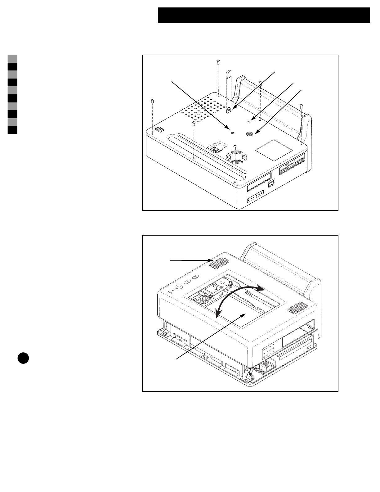
Step 3
Remove the 6 black pan-head torx screws
with a T-15 driver, as shown in Figure 2a.
Step 4
See Figure 3. Carefully position the unit so
that the LCD panel (Detail 7) is face up.
Avoid bending the metal lock tab (Detail 4)
on the back of the unit.
NOTE: Elevating the unit on two boards
will prevent damage to the metal lock tab.
Lift the upper housing (Detail 63) from the
computer assembly to access the interior.
Slightly rotate the stand higher than the top
of the LCD panel to release the upper hous-
ing (Detail 63) from the computer. (The
upper housing fits tightly, so slight rota-
tions, as depicted by the arrow heads in
Figure 3, might be required to remove the
upper housing completely.
Figure 3
Figure 2a
3
63
4
21
7
lock tab
cover
Table des matières
Manuels Matériel informatique populaires d'autres marques

EMC2
EMC2 VNX Series Manuel du propriétaire

Panasonic
Panasonic DV0PM20105 Manuel utilisateur

Mitsubishi Electric
Mitsubishi Electric Q81BD-J61BT11 Manuel utilisateur

Gigabyte
Gigabyte B660M DS3H AX DDR4 Manuel utilisateur

Raidon
Raidon iT2300 Manuel utilisateur

National Instruments
National Instruments PXI-8186 Manuel utilisateur


