MiSensors MNG-9-2A2V Manuel utilisateur

MiSensors Cellular Gateway Quick Start
• Create an MiSensors user account and assign wireless gateway and sensors.
• Plug the power supply into a power outlet then connect to the gateway.
• Turn the power switch on (battery backup models only).
• Once all three lights turn green, your network is ready to bring sensors online.
IMPORTANT!
DO NOT power up your Cellular Gateway until after you have created an account on
login.misensors.com and added your cellular gateway and wireless sensors to the account.
MiSensors Wireless Sensors
and Cellular Gateway
User’s Guide
For MiSensors Cellular Gateway
Use With MiSensors Online Software

1. Create a MiSensors User Account and Setup Sensor Network
If this is your rst time using the MiSensors online system site, you will need to create a
new account. If you have already created an account you can skip to the “Logging into the
Online System” section. The following instructions will guide you through the account
creation process.
1. In a web browser, navigate to https://www.login.misensors.com.
2. Click the “Get Started Here” button to create an account.
3. Follow the on-screen instructions to enter your account and contact
information.
4. After entering your account and contact information, you will be prompted to
create your rst sensor network. Simply enter a name for this network.
5. Add the information from your MiSensors gateway then click the
“Assign Gateway” button.
Contains FCC ID: ZTL-RFSC1
and IC: 9794A-RFSC1
This device complies with Part 15 of the
FCC Rules. Operation is subject to the
following two conditions:
(1) this device may not cause harmful
interference and
(2) this device must accept any interference
received, including interference that may
cause undesired operation.
ID: ######
Code: XXXXXX
6a. Add the information from your rst MiSensors wireless sensor then click the
“Assign Sensor” button.
+
_
Back of Sensor
Peel
Contains: FCC ID: ZTL-RFSC1
IC: 9794A-RFSC1
Sensor ID: ######
Sensor Code: XXXXXX
6b. On the next screen, enter a name for the wireless sensor and use the
drop down to tell us how you are going to be using the wireless sensor.
(This allows us to suggest settings for your sensor.) When nished, click
the “Continue” button.
PAGE 2

PAGE 3
7. Conrmation Screen.
When you have nished adding the sensor, you will see a conrmation screen. At this
point you can assign notications to the sensor (see Using The MiSensors Online Wire-
less Sensor System) , assign additional sensors to your account or click “Done” to go to
your sensors overview page.
2. Using the MiSensors Cellular Gateway
1. Using the MiSensors Cellular Gateway
• Attach the Antenna’s to the gateway (Sensor RF antenna on left, Cellular on right).
• Plug the power supply into a power outlet then connect to the gateway.
• Turn the power switch on (battery backup models only)
• Check that the three LED lights on the front of the gateway change to green. Once all
three lights turn green, your network is ready to use.
2. Understanding the Cellular Gateway Lights
Sensor communication problem
Communication with sensors is ok
Blinking: active communication between sensors and gateway
Last communication with MiSensors server was unsuccessful
Last communication with MiSensors server was ok
Blinking: active communication with MiSensors server
Cellular network connection error
Blinking Red: Network registration in progress
Connected to the cellular network
Blinking Green: Activating data session
Blinking Green / Red: Low cellular network signal
Note 1: The cellular gateway resets itself after receiving new conguration from the server
(ex. new HB), the LEDs will change colors briey, then each LED will ash red as the
gateway connects. When all LEDs have turned green, the reset cycle has completed.
Note 2: During SW upgrade, the middle LED will ash green. After successful upgrade all
LEDs will ash green, then the gateway will restart.
Note 3: Units with battery backup will turn o the LEDs when running on battery power to save on
power consumption. LEDs will ash to signify activity then go o again. When power is
restored, operation will return to normal.
CellularSensor RF

On Boot-up: The cell light begins flashing red. The flashing switches to green and
nally lands on a solid green when the link to the cell network is established. Next, the
middle light ashes green and then lands on solid green when the link to the server is
established. The wireless sensor light turns green indicating the gateway is ready to
listen to sensor trac.
During Operation: All lights are solid green. Activity from a sensor will cause the wire-
less sensor light to ash instantly. When the gateway is deliver messages to the server,
the cell light may illuminate and go through the sequence of acquiring a link to a tower if
it is not currently connected. The middle light ashes green on the gateway’s heartbeat,
or when an urgent message needs delivery.
2. Cellular Gateway Controls
Control Button
A short press of the control button while lights are all green, will force immediate
communication to server and exchange all sensor data currently stored in memory.
Press and hold to reset the gateway to factory settings (hold until all lights go red).
This resets the gateway heartbeat to 60 minutes. You will need to login to the online
system after resetting the gateway to recongure the gateway to your desired settings.
Note: If the gateway LEDs do not turn green, you may have a connectivity issue. Wait a few
minutes to see if the lights turn green. If they do not, power cycle the device by disconnecting
then reconnecting the power on standard gateways or toggling the power switch on gateways with
battery backup. If it still does not connect, reset the device to factory settings. If there is still an
issue, contact MiSensors customer support. If all three lights look amber, then there is an internal
hardware problem. If, left to right, the lights are red-green-green, there is a cell modem issue. If
red-red-green, there is a memory issue. For all of these cases, you will need to contact MiSensors
support at www.misensors.com/support or call 1.844.464.7367.
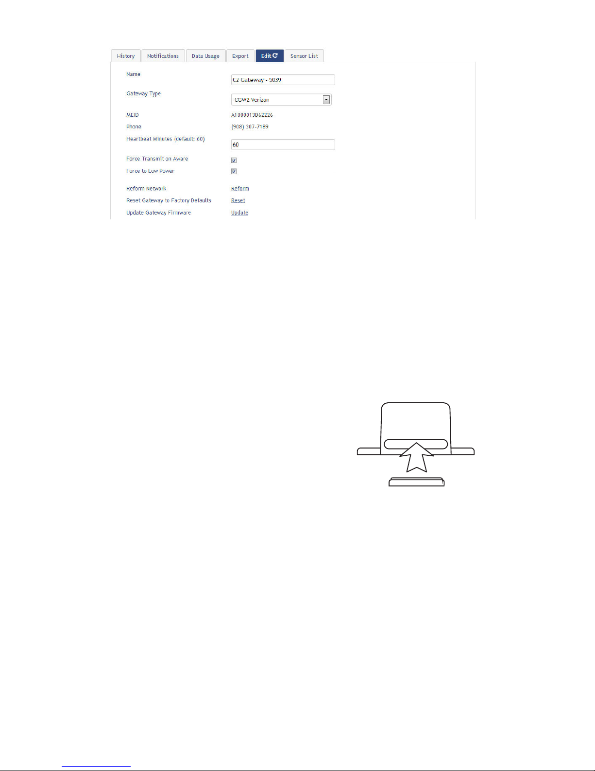
3. Conguring The Cellular Gateway
The cellular gateway collects data from all sensors within range and is precongured
to batch deliver the sensor messages to the online system at the specied heartbeat
(every 60 minutes by default factory settings).
You can access gateway settings by clicking on “View Gateways” in the top bar of the
“Overview” page. Clicking on a gateway in the list, opens the detail view. Click on the
“Edit” tab to access the gateway’s settings.
PAGE 4
3. Using Your MiSensors Wireless Sensors
Insert Batteries Into Wireless Sensors
Important: Make sure your sensors are at least 3ft. away from Ethernet Gateway.
Peel back the black sticker cover of the battery slot and slide the coin cell battery into
the sensor as shown in g.1. It will power on within 10-20 seconds. Once online, your
sensor is ready to be deployed. If you wish to change a sensor conguration, change the
parameter in the software. The new parameters will be transmitted to the sensor on the
next heartbeat. If you need a more immediate response from the sensor, power cycle the
sensor by removing the battery, waiting 60 seconds, then re-insert the battery.
Notes:
- If the sensor status indicator does not change, reset
the sensor by removing the battery.
- Wait 60 seconds then re-insert the battery.
- When inserting the battery, make sure to push the
battery all the way back using a paper clip.
- Note the proper orientation of battery in g.1
Warning: Your sensors ship with a 10-minute heartbeat.
It is recommended that unless you are using the AA battery
solution, you should set the heartbeat to no faster than one hour to preserve battery life. When
changing a sensor’s heartbeat, the new configuration information will be sent to the sensor on its next
heartbeat. If you want to update the sensors immediately you can reset them manually.
Manual Sensor Reset Process:
1 - Using the end of a paper clip, push the batteries out of the sensors through the small hole
in the top of the sensor
2 - Change the sensor heartbeat through the online system
3 - Re-insert the batteries into the sensors
+
_
Battery
Insertion
g.1
PAGE 5

PAGE 6
4. Using The MiSensors Online Wireless Sensor System
1. Understanding The Online Interface
When you log into the online system, the default view shows all of your sensors last
recorded data.
View / Sort FeaturesMenu System
Sensor Details ViewSensors Overview
Date Range Selector
Menu System
Overview - Shows all sensors in the account and their last readings.
Notications - Manage sensor notications and show all sent notications.
Manage - Manage networks, sensors and gateways.
Reports - Printable account and sensor network reports.
Sensor Maps - Visual maps to help you track sensor placement.
Support - Support information for using sensors and software.
View / Sort Features
This section allows you to sort the sensors being viewed and search for sensors on
your account.
Sensor Overview
Displays sensors on your account with their last reading and status information.
Clicking on a sensor row expands the “Sensor Detail View” allowing you to view
detailed information for the selected sensor.

PAGE 7
To the left side of each sensor row is an indicator to help you understand the current
status of the sensor.
Sensor is checking in and within user-defined safe parameters.
Sensor has met or exceeded a user dened threshold or triggered event.
Sensor has not checked in (inactivity alert sent).
No sensor readings will be recorded (Inactive)
Sensor Details View
Clicking on a sensor row on the “Overview” page expands the row to include a detailed
sensor view for the selected sensor.
Select a tab to change between:
History - Displays a history of the selected sensor’s data.
Chart - Displays a graphical view of the selected sensor’s data.
Notications - Allows you to manage notications for the sensor.
Export - Allows you to archive data by exporting as a .csv le.
Edit - Allows you to manage sensor settings.
Calibrate - Available on certain sensor types to provide more accurate data.
Note: The data shown on the chart, notication, history and export tabs is based on the date
range indicated on the upper right side of the sensor detail information. To change the date
range, click inside the date box.
2. History and Chart Views.
Clicking on the “History” or “Chart” tabs within the sensor detail panel allows you to view
the sensor’s data history as time stamped data or in a graphical chart format.
Note: To change the date range of the viewable information, click on
the date range box at the top right of the sensor detail panel.

PAGE 8
3. Conguring Sensor Settings
To edit a sensors operation settings, click on the sensor overview row to display the
details view. Click on the “Edit” tab to access the sensor conguration panel.
The sensor edit panel allows you to set the primary configurations for the sensor.
Hovering your cursor over the question mark icon by each setting will provide an
explanation of that setting. When you have finished making changes, press the “Save”
button at the bottom of this section.
Note: Be sure to click the “Save” button anytime you make a change to any of the sensor parameters.
All changes made to the sensor settings will be downloaded to the sensor on the next sensor
heartbeat (check-in). Once a change has been made and “Saved,” you will not be able to edit that
sensor’s configurations again until the sensor has downloaded the new setting.

4. Sensor and/or Gateway Notication(s).
Notications for a single sensor can be created, deleted or edited by clicking the
“Notications” tab in a sensor’s detail view.
Notications can be created, deleted or edited for any sensor or group of sensors by
clicking on “Notications” in the main menu.
Toggle On/O Click to Open Detail View Send Test Edit Delete
When creating a notication, you will need to select the type of notication to create.
•Sensor Reading Notication - Reading notications are sensor specic (i.e. water
sensor = trigger alert when water present, temp sensor = trigger alert when temp
is above 70F, etc.). When creating a sensor reading notication, you will need to
choose the sensor type you are creating the alert for. The select box will only show
sensor types that are currently being used on your sensor network.
•Battery Notication - Allows users to dene a battery power percentage level that
will trigger an alert from the system, warning them to replace batteries.
•Inactivity Notication - Set-up “Inactivity” notications to alert you when your sen-
sors have stopped communicating with the servers. Failure to set up an “Inactivity”
notication will result in no email/SMS text being sent should your sensors stop
communicating with the servers.
PAGE 9

PAGE 10
•Advanced Notications - Allows the user to set notications based on advanced
rules, such as comparing past data points with the current one to determine if a
notication should be sent.
•Existing Notications - Use notications that have already been created on your
account with the selected sensor.
Notication Settings
This area allows the user to set notication parameters such as naming the
notication, customizing the notication message and setting sensor conditions that will
trigger the notication.
People to Notify
The list on the left shows all available users on the account. You can type into the
search box to lter large lists of users. Select the user(s) to receive the notication and
click the arrow button to add them to the recipient list. By default, email notications are
activated. Clicking the notication delivery method icon toggles them on and o (green
is on, grey is o). If the user should receive text message notications, click on the
phone icon to turn it green.
Sent From
Allows you to assign devices (sensors and gateways) that will cause the notication
to be sent. When a notication is sent from the system, it will automatically include the
device name and the data that caused the notication to be sent. A single notication
can be assigned to multiple sensors or gateways. Sensor reading notications can only
be assigned to sensors of the same type. General notications such as “battery status”,
can be assigned to any or all sensors.
Ce manuel convient aux modèles suivants
5
Table des matières
Manuels Porte populaires d'autres marques

LST
LST M500RFE-AS Manuel utilisateur

Kinnex
Kinnex Media Gateway Manuel utilisateur

2N Telekomunikace
2N Telekomunikace 2N StarGate Manuel utilisateur

Mitsubishi Heavy Industries
Mitsubishi Heavy Industries Superlink SC-WBGW256 Manuel utilisateur

ZyXEL Communications
ZyXEL Communications ZYWALL2 ET 2WE Manuel utilisateur

Telsey
Telsey CPVA 500 - SIP Manuel utilisateur


