SERVICE - UISpage 5
3. Repair instructions
These instructions describe service and maintenance operations as well as steps for dismantling of BASIC,
EXCELLENT and PERFECT ovens.
Unless otherwise described, assembly takes place in the reverse order.
Alterations in technical matters are reserved. Measurements are not binding.
4. Fault finding and error messages
Fault details
Fault cause
Fault rectification
Section
General faults
Controller display
remains dark
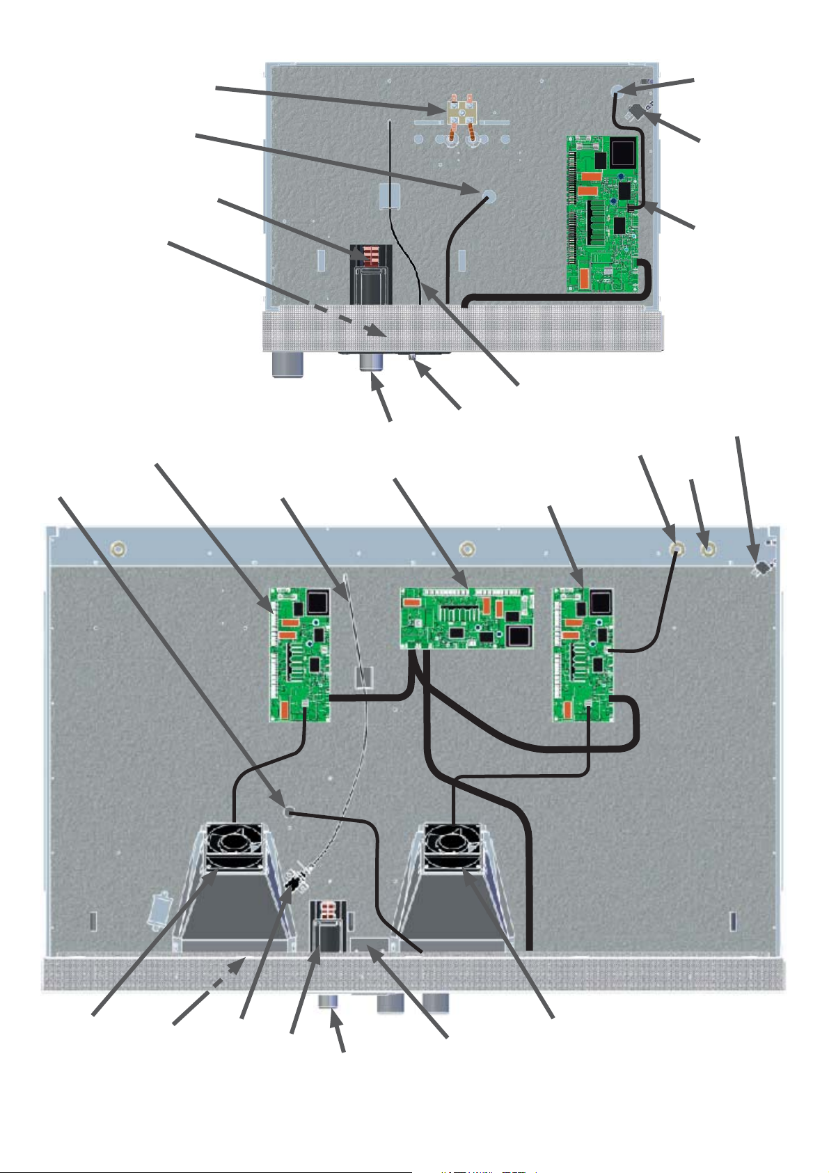
Fuse 100 mA (80 mA) has blown Check fuse and replace if nec. Section 9
Main fuse 15 A has blown Check fuse and replace if nec. Section 9
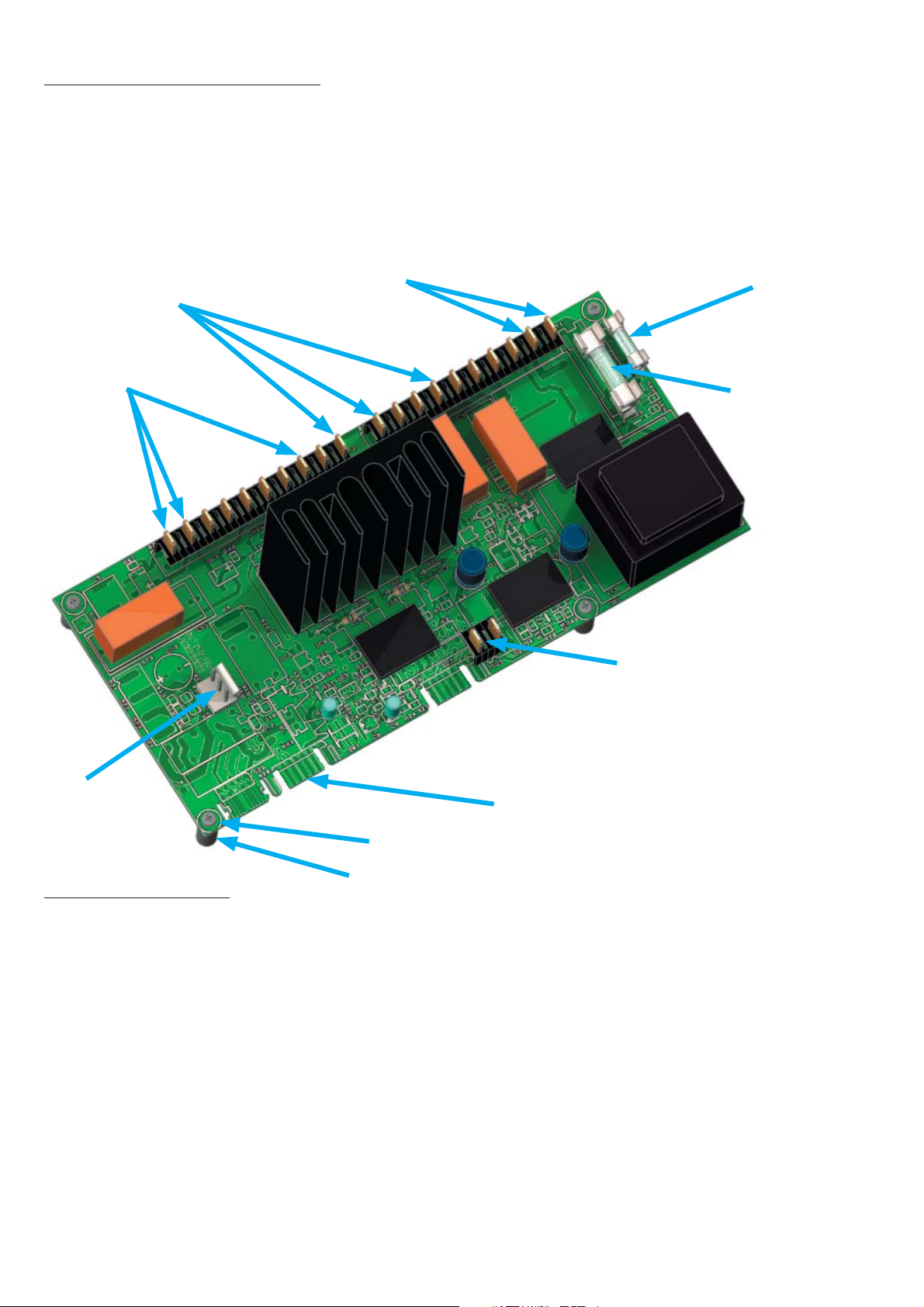
Power unit faulty Replace power unit Section 8
Temperature can not be
set and oven can not
be operated by turn
control.
Turn control faulty Replace main switch module incl. turn control Section 10
Oven “blocked” by UserID card Unblock using UserID card siehe
Betriebs-
anleitung
Error messages in monitor indication
Error messages in monitor indication
Warning – symbol
alight continuously
Mechanical-action temperature limiter has switched off
the heating
- Switch off oven and allow to cool down.
- Check Pt100 temperature probe.
- Check temperature limiter
- The oven is again ready for operation only after fault
has been rectified and the oven has cooled down.
Section 14
Warning – symbol
flashing
Monitor controller has switched off the heating because
temperature difference
between working controller and monitor controller is
too small.
Increase temperature difference between monitor
temperature and working temperature.
If nec. replace Pt100 temperature probe on monitor
controller
Section 16
Error message „E-3“ Pt100 temperature probe of monitor controller is
faulty.
Replace Pt100 temperature probe of monitor controller
on connector J3
Section 16
Error message
„E-3” alternating with
temperature display
Pt100 temperature probe of monitor controller is
faulty. Monitor controller operates in emergency mode
with temperature value of working controller Pt100
temperature probe
Replace Pt100 temperature probe of monitor controller
on connector J3.
Section 16
Error message in timer display
Error message in timer display
Error message „E-0“ Serious configuration error (e.g. incorrect oven type or
incorrect temperature range)
Replace controller Section 11-
13
Error message „CONF”
(display only appr. 10
sec after switching on)
Checksum error (error on storing the setpoints, e.g. fan
speed)
The fault can be rectified by the controller itself after
repeating the storage function of a setpoint parameter.
If the fault is repeated or can not be rectified, the
controller has to be replaced
Section 11-
13
Error message „E-L1” in
timer display
Interruption in communication to power unit Check connecting cable.
If nec. replace power unit
Section 8
Error messages in temperature display
Error messages in temperature display
Error message „E-3” Pt100 temperature probe of working controller faulty Replace Pt100 temperature probe of working controller
on connector J4
Section 16
Error message „E-3”
alternating with
temperature display
Pt100 temperature probe of working controller is
faulty. Working controller operates in emergency mode
with the temperature value of monitor controller Pt100
temperature probe.
Replace Pt100 temperature probe of working controller
on connector J4.
Section 16
Error message „E-1.1” Power unit triac 1 faulty Replace power unit Section 8
Error message „E-1.2” Power unit triac 2 faulty Replace power unit Section 8
Error message „E-2.1” Power unit faulty Replace power unit Section 8
Error message „E-2.2” Power unit faulty Replace power unit Section 8