Medion MD 9901 Manuel utilisateur

CHAPTER 1 INTRODUCTION
1-1
The MICRO ATX ZX mainboard is a high-performance personal computer
mainboard based on the Intel®Pentium®II/Pentium®III/CeleronTM processor.
This mainboard combines leading edge nVIDIA Riva TNT2 M64 technology
in graphics and Creative®ES1373 PCI technology in audio. The Intel®
Pentium®II/III/CeleronTMprocessor supports MMXTM (Multimedia Exten-
sion) technology.
The mainboard uses the highly integrated Intel®82443ZX AGP chipset to
support the PCI/ISA and Green standards, and to provide the Host/AGP
bridge. The Intel®82371EB chipset integrates all system control functions
such as ACPI (Advanced Configuration and Power Interface). The ACPI
provides more Energy Saving Features for the OSPM(OS Direct Power
Management) function. The Intel®82371EB chipset also improves the IDE
transfer rate by supporting Ultra DMA/33 IDE that transfers data at the rate
of33MB/s.
The mainboard also supports the System Hardware Monitor Controller as an
optional function. Its functions include: CPU /power supply/chassis fan
revolution detect, CPU/system voltage monitor, system temperature monitor,
and chassis intrusion detect(optional).
Chapter 1
INTRODUCTION

CHAPTER 1 INTRODUCTION
1-2
1.1 Mainboard Features
CPU
lSlot 1 for Intel®Pentium®II/Pentium®III/CeleronTM processor.
lSupports233MHz,266MHz,300MHz,333MHz,350MHz,400MHz,
450MHz,500MHzand faster.
Chipset
lIntel®440ZXAGPset
- support 66 or 100Mhz Host bus frequency
- support AGP & PCI
lIntel®PIIX4Echipset
-PCI to ISABridgePC98Compliant
-UltraDMA-33MasterModePCI IDE Controller
- Super I/O Interface
- 324 pin BGA package
FSB(FrontSideBus)
l66.6MHz and 100MHz clocks are supported.
MainMemory
lSupports four memory banks using two 168-pin unbuffered DIMM.
lSupportsamaximum memorysizeof256MB (8Mx8).
lSupports 3.3v SDRAM DIMM.
Slots
lThree 32-bit Master PCI Bus slots
lSupports 3.3v/5v PCI bus Interface.
On-BoardIDE
lAn IDE controller on the Intel®PIIX4E PCI Chipset provides IDE HDD/
CD-ROM with PIO, Bus Master and Ultra DMA/33 operation modes.
lCan connect up to four IDE devices.

CHAPTER 1 INTRODUCTION
1-3
On-BoardPeripherals
lOn-Board Peripherals include:
- 1 floppy port supports 2 FDD with 360K, 720K, 1.2M, 1.44M and
2.88Mbytes.
- 1 serial port (COM A) + 1 serial connector (COM B)
- 1 parallel port supports SPP/EPP/ECP mode
-1MIDI/Game Port
- 2 USB ports
-1IrDAconnectorforSIR/FIR.
- 1 Audio port (Line_In, Line_Out, and Mic_In Jack)
-1VGAport
VGA
lnVIDIARivaTNT2M64
- Running on AGPBUS.
-Onboard32MB(4*16M) SDRAM.
- 3D Acceleration.
- AGP 2x mode support pipelined protocols.
Sound
lCreative®ES1373
-RunningonPCIBUS.
- Support Direct Sound and Direct Sound 3D
-AC97’Compliant
BIOS
lThe mainboard BIOS provides “Plug & Play” BIOS which detects the
peripheral devices and expansion cards of the board automatically.
lThe mainboard provides a Desktop Management Interface(DMI) function
which records your mainboard specifications.
lACPI(Advanced Configuration and Power Interface) feature.
Dimension
lMICRO-ATXFormFactor: 24.4cm(L)x 20.6cm(W)x 4 layersPCB

CHAPTER 1 INTRODUCTION
1-4
Mounting
l6 mounting holes.
SystemHardwareMonitor(optional)
lCPU/Power Supply/Chassis Fan Revolution Detect
lCPU Fan Control (the fan will automatically stop when the system enters
suspend mode)
lSystem Voltage Detect
lCPU Overheat Warning.
lDisplay Actual Current Voltage
OtherFeatures
lKeyboard Password Wake-Up (reserved)
lLAN Wake-Up
lInternal/External Modem Wake-Up

CHAPTER 1 INTRODUCTION
1-5
PCI SLOT 3
PCI SLOT 2
PCI SLOT 1
ATX
Power Supply
FW82443ZX
SLOT 1
DIMM 2
Top: Mouse
Top:Port1
USB
DIMM 1
IDE2
Bottom:
Port2
IDE1
FDD
FW82371EB
JMDM1
Creative
ES1373
JFP
JGS1
JGL1
BIOS
J5: MDM_IN
J7: AUX_IN
COM 2
CPUFAN
JRMS1
SW1
IR
BATT
+
Top: LPT
Bottom:
COMA
VGAPort
Top: Midi/
GamePort
Bottom:
Line-Out
Line-In
Mic
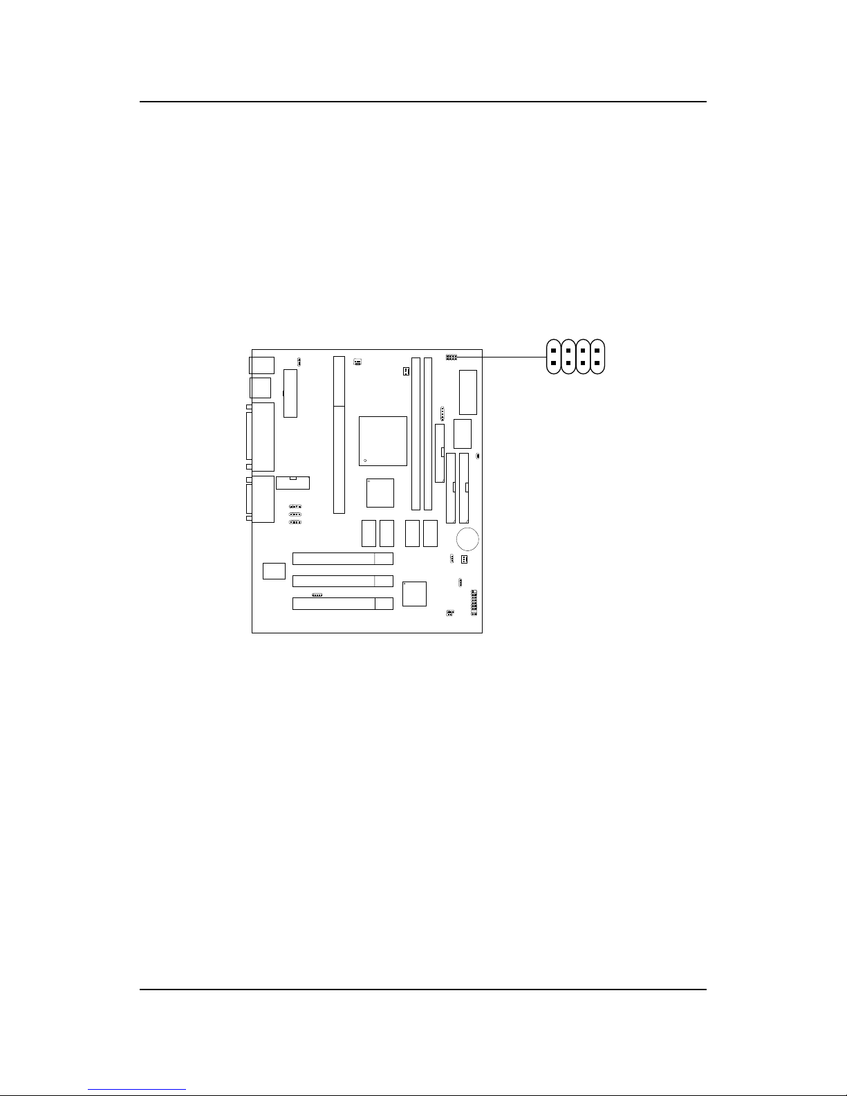
1.2 Mainboard Layout
14
J8: CD_IN
SDRAM
JVSB1
(Reserved)
SDRAM
SDRAM SDRAM
Bottom:
Keyboard PSFAN
W83977EF-AW
SYSFAN
JWOL
JBAT1
nVIDIA
RivaTNT2
M64
Medion9901MICROATX ZX Mainboard

CHAPTER 2 HARDWARE INSTALLATION
2-1
Chapter 2
HARDWARE INSTALLATION
2.1 Central Processing Unit: CPU
Step 1: Install the Retention Mechanism.
Attach the Retention Mechanism to the Mainboard. Push the Plastic
lock to secure the Retention Mechanism into the mainboard.
Secure the processor by
pulling up the Retention
Mechanism Processor
Lock
Insert the processor
like inserting a PCI or
an ISA card
To release the
processor, push the
Retention Mechanism
Processor lock down
Step 2: Install the Processor.
Insert the Processor like inserting a PCI or an ISA card.
Step 3: Lock the Processor.
Lock the processor by pulling up the Retention Mechanism proces-
sor lock shown above.
Note: The Retention Mechanism processor lock can only lock S.E.C.C. 2
and S.E.P.P. processor.
2.1-1 Processor Installation Procedures

CHAPTER 2 HARDWARE INSTALLATION
2-2
2.1-2 CPU Core Speed Derivation Procedure
1 2 3 4 Core/Bus Ratio
ON OFF ON ON 2.5
ON ON OFF ON 3
ON OFF OFF ON 3.5
ON ON ON OFF 4
ON OFF ON OFF 4.5
ON ON OFF OFF 5
ON OFF OFF OFF 5.5
OFF ON ON ON 6
OFF OFF ON ON 6.5
OFF ON OFF ON 7
OFF OFF OFF ON 7.5
OFF ON ON OFF 8
1. The DIP Switch SW1 (1, 2, 3, and 4) is used to set the Core/Bus (Fraction)
ratio of the CPU. The actual core speed of the CPU is the Host Clock
Frequency multiplied by the Core/Bus ratio. For example:
If CPUClock = 66MHz/100MHz
Core/Bus ratio = 4
then CPU core speed = Host Clock x Core/Busratio
= 66MHzx 4/100MHzx4
= 266MHz/400MHz
SW1 CPU
Note: The CPU Bus Frequency is set at 66MHz or 100MHz by CPU
default.
ON-Short OFF- Open
CHAPTER 2 HARDWARE INSTALLATION
2-3
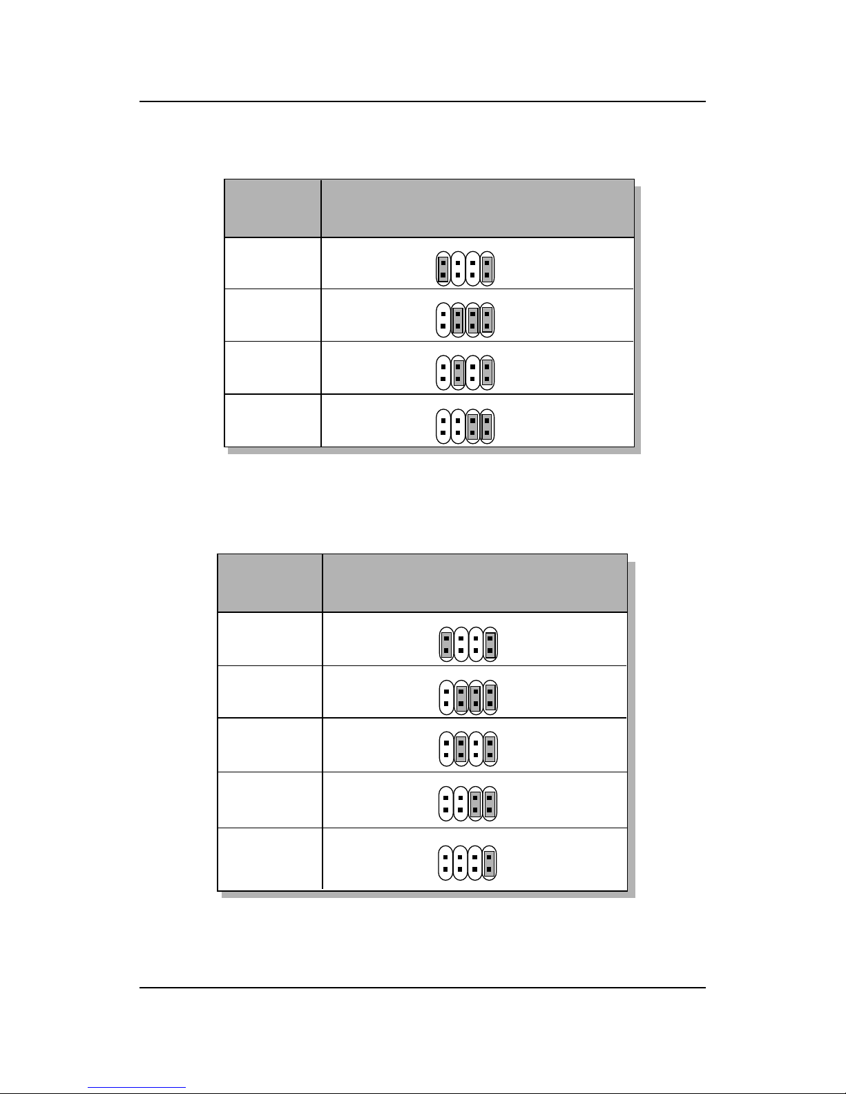
2.1-3 CPU Speed Setting: SW1
To adjust the speed of the CPU, you must know the specification of your
CPU (always ask the vendor for CPU specification). The mainboard can
auto-detect between 66 or 100MHz CPU Bus Frequency.
SW1
123
4
CHAPTER 2 HARDWARE INSTALLATION
2-4
400MHz
450MHz
350MHz
CPU
Type SW1
b. 100MHz CPUBusFrequency
Table 2.1 233 ~ 333MHz Intel®Pentium®II/III/CeleronTM
processor
233MHz
266MHz
300MHz
333MHz
CPU
Type SW1
a. 66MHz CPUBusFrequency
123
4
123
4
123
4
123
4
123
4
123
4
123
4
500MHz
550MHz
123
4
Table 2.2 350 ~ 550MHz Intel®Pentium®II/III processor
123
4

CHAPTER 2 HARDWARE INSTALLATION
2-5
SENSOR
+12V
GND
CPUFAN
2.1-4 Fan Power Connectors: CPUFAN/PSFAN/SYSFAN
These connectors support system cooling fan with + 12V. It supports three
pin head connector. When connecting the wire to the connector, always
take note that the red wire is the positive and should be connected to the
+12V, the black wire is Ground and should be connected to GND. If your
mainboard has System Hardware Monitor chipset on-board, you must use a
specially designed fan with speed sensor to take advantage of this function.
+12V
SENSOR
GND
PSFAN
SYSFAN
+12V
SENSOR
GND
PSFAN: PowerSupply Fan
CPUFAN: ProcessorFan
SYSFAN: System(Chassis) Fan
For fans with fan speed sensor, every rotation of the fan will send out 2
pulses. System Hardware Monitor will count and report the fan rotation
speed.
Note: 1. Always consult vendor for proper CPU cooling fan.
2. CPU FAN supports the FAN control. You can install PC Alert
utility. This will automatically control the CPU FAN Speed according
to the actual CPU temperature.
Ce manuel convient aux modèles suivants
1
Table des matières
Autres manuels Medion Carte mère


Manuels Carte mère populaires d'autres marques


Telit Wireless Solutions
Telit Wireless Solutions SL869-3DR Manuel utilisateur

Gigabyte
Gigabyte GA-9IVDT Manuel utilisateur

Texas Instruments
Texas Instruments ADS8372EVM Manuel utilisateur

Commell
Commell MS-C73 Manuel utilisateur

IBT Technologies
IBT Technologies MB860 Manuel utilisateur

Nvidia
Nvidia TEGRA DG-04927-001_V01 Manuel utilisateur


