
Mac allister M-4545CSP Manuel utilisateur

Original Instructions_MNL_M-4545CSP_GB_V03_111107
M-4545CSP
45cc Petrol
Chain Saw
Barcode: 5052931013852
MNL_M-4545CSP_DFT_GB_V4_111107.indd 1 11/7/11 11:36:55 AM
Supported by
For all your Warranty,
Parts and Service needs
0845 601 4221
www.servicelink.org.uk
GB
IE
02
45
46
60
61
43
25
33
20
In more detail...
Product functions
Operation
Care and maintenance
Trouble shooting
Recycling and disposal
Technical and legal information
Guarantee
EC declaration of conformity
19
03
03
15
18
Getting started...
Before you start
Quick Start
Safety
These instructions are for your safety. Please read through them
thoroughly before use and retain them for future reference.
Let’s
get started...
MNL_M-4545CSP_DFT_GB_V4_111107.indd 2 11/7/11 11:36:55 AM
M-4545CSP by MacAllister
Getting started...
GB
IE
03
Before you start
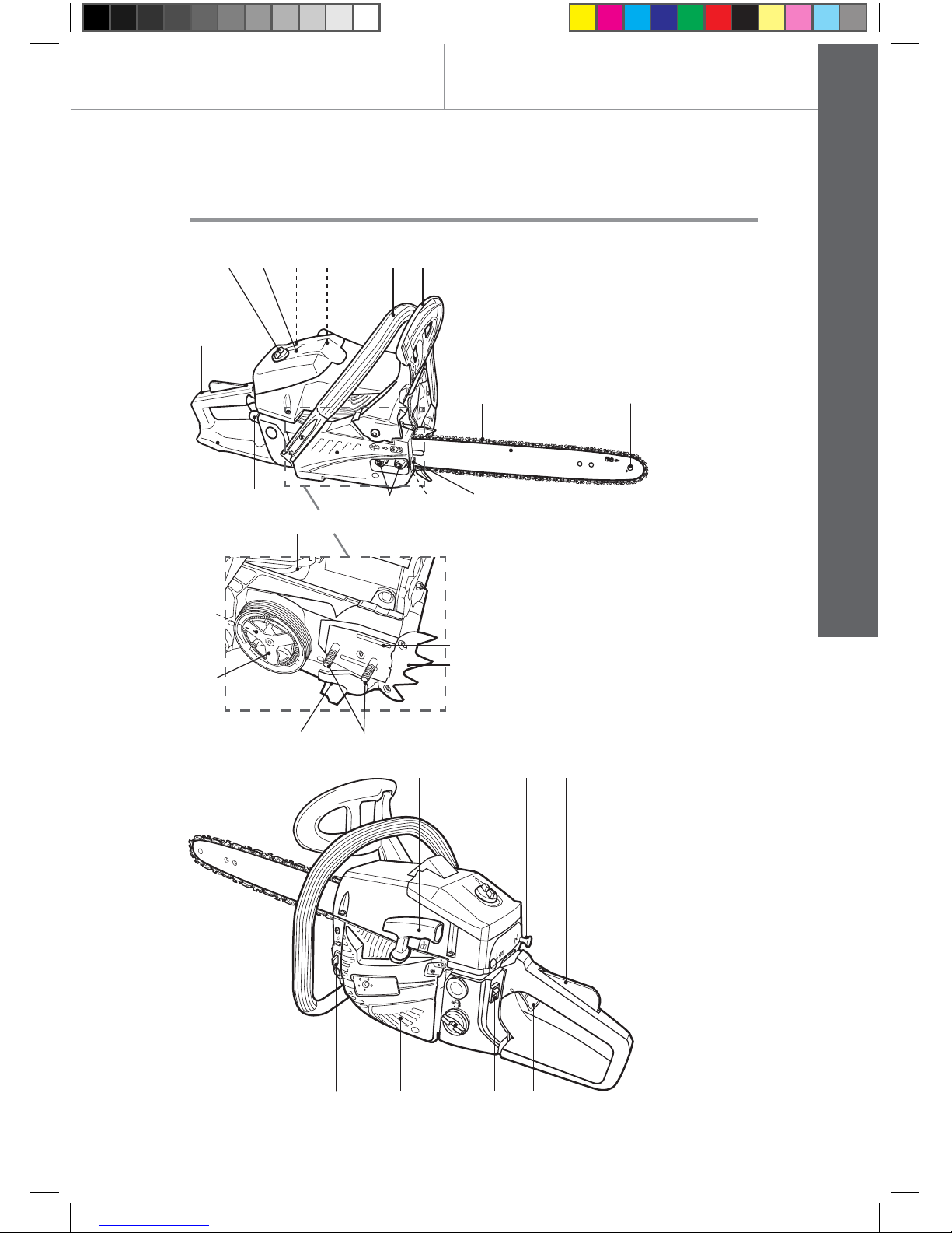
Your product
20
1
11
10 9 8 7 6a 6
23 24 25
2627282930
2151412 13
3 4 5
16
18
22
19
17
21
MNL_M-4545CSP_DFT_GB_V4_111107.indd 3 11/7/11 11:36:56 AM

04
M-4545CSP by MacAllister
Getting started...
GB
IE
Your product
Before you start
31 32 33
34
1. Front handle
2. Front guard/chain
brake
3. Saw chain
4. Guide bar
5. Sprocket nose
6. Tension screw
a. Tension pin
7. Retaining nut
8. Cover
9. Primer
10. Rear guard
11. Rear handle
12. Fixing screw
13. Air filter cove
14. Air filte
15. Spark plug connector
16. Cylinder fin
17. Oiling port
18. Spike bumper
19. Support pin
20. Chain catcher
21. Clutch
22. Drive sprocket
23. Recoil starter handle
24. Choke knob
25. Throttle interlock
26. Throttle trigger
27. Ignition switch (on/off)
28. Fuel tank cap
29. Air vents
30. Chain oil tank cap
31. Storage box
32. Combination spanner/
Spark plug wrench
33. Guide bar cover
34. Sharpening kit with
instruction manual
MNL_M-4545CSP_DFT_GB_V4_111107.indd 4 11/7/11 11:36:58 AM

M-4545CSP by MacAllister
Getting started...
GB
IE
05
Before you start
Pull the latches to open the cover (Fig. 1, 2). >
Pull the front part downwards (Fig. 3). >
Remove the product from the box (Fig. 4). >
Fig. 1 Fig. 2
Fig. 3 Fig. 4
Unpack all parts and lay them on a flat, stable surface >
Remove all packing materials and shipping devices if >
applicable.
Make sure the delivery contents are complete and free of any >
damage. If you find that parts are missing or show damage do not
use the product but contact your dealer. Using an incomplete or
damaged product represents a hazard to people and property.
Ensure that you have all the accessories and tools needed for >
assembly and operation. This also includes suitable personal
protective equipment.
Unpack
NOTE: This product comes in a box, keep it for storage.
MNL_M-4545CSP_DFT_GB_V4_111107.indd 5 11/7/11 11:36:59 AM
06
M-4545CSP by MacAllister Before you start
Getting started...
GB
IE
You will need
WARNING! Although the product comes fully assembled
it is essential to ensure it is free of any damage! Therefore
carefully check the product before operation!
WARNING! Before removing, ensure the front guard/
chain brake (2) is in the disengaged position (see section
“In more Detail - Chain brake”). If in the engaged position,
pull the front guard/chain brake backwards until it ‘clicks’
into position.
(items not supplied)
Petrol
Engine oil
Fuel funnel with filte
Saw chain oil
Lubrication oil
(items supplied)
Saw chain
Guide bar cover
Sharpening kit with
instruction manual
Disconnect the spark plug connector (15) from the spark plug.
Place the product on a suitable flat surface with the cover (8) >
facing upwards.
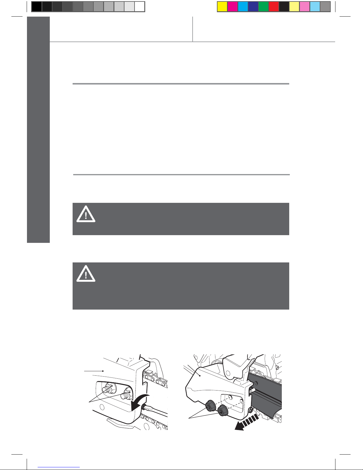
Ensure the saw chain (3) is loose, turn the tension screw >
anticlockwise with a screwdriver, if required (Fig. 5).
Use the combination spanner (32) to loosen the retaining nuts >
(7) from the cover (8) and remove them together with the cover
(Fig. 6).
8
7
7
8
Fig. 5 Fig. 6
Assembly
MNL_M-4545CSP_DFT_GB_V4_111107.indd 6 11/7/11 11:37:00 AM

M-4545CSP by MacAllister
Getting started...
GB
IE
07
Before you start
Remove the guide bar (4) and saw chain (3) from the drive >
sprocket (22) and support pins (19) (Fig. 6).
Check the area under the cover (8), around the clutch (21), drive >
sprocket (22) and support pins (19) and ensure that they are
free of any damage.
Chain and guide bar
Re-assemble the guide bar (4) and saw chain (3) before operation.
Follow the operating instructions step-by-step and use the pictures
provided as a visual guide to easily assemble the product.
Use only a guide bar (4) and saw chain (3) according to the >
technical data of this product.
WARNING! Always use a saw chain designed as “low-
kickback” or a saw chain which meets the low-kickback
requirements! A standard saw chain (a chain which does
not have the kickback reducing guard links) should only
be used by an experienced professional operator!
Nevertheless, a low-kickback saw chain does not
completely eliminated kickback! A low-kickback or “safety”
chain should never be regarded as complete protection
against injury! Therefore always use a low-kickback saw
chain in conjunction with other kickback protection devices
such as the front guard/chain brake!
Place the slot in the guide bar (4) over the supporting pins (19). >
Push the guide bar (4) to the left towards the drive sprocket (22)
(behind the clutch (21)) (Fig. 7).
Spread the saw chain (3) over the sprocket (22) behind the >
clutch (21) and fit around the guide bar (4) with the cutting edges
of the chain pointing in the rotational direction (Fig. 8).
21
19 4
Fig. 7 Fig. 8
MNL_M-4545CSP_DFT_GB_V4_111107.indd 7 11/7/11 11:37:01 AM

08
M-4545CSP by MacAllister
Getting started...
GB
IE
Before you start
Assembly
WARNING! The direction of the saw chain ‘cutters’ must
be as indicated by the symbol and arrow on the guide
bar!
Slide the chain into the groove >
around the guide bar (Fig. 9). 5
Fig. 9
Make sure the chain is placed above the chain catcher (20) >
(Fig. 10).
Pull the guide bar (4) carefully towards the right to pre-tighten >
the saw chain (3) (Fig. 11).
20
20
Fig. 10 Fig. 11
Refit the cover (8) and fix it with >
the retaining nuts (7). Make sure
the tension pin (6a) is inserted
into the lower hole on the guide
bar (Fig. 12). 7
8
6
Fig. 12
MNL_M-4545CSP_DFT_GB_V4_111107.indd 8 11/7/11 11:37:02 AM

M-4545CSP by MacAllister
Getting started...
GB
IE
09
Before you start
NOTE: Fix the nuts finger tight only at this stage. The
chain tension can not be adjusted with the retaining nuts
tightened - they must be loosened first
NOTE: The saw chain (3) has not yet been tensioned.
Tension the chain as described under “Saw chain
tensioning”. After operating the product for approximately
1 hour, adjust the chain tension again.
Saw chain tensioning
Always check the saw chain tension before use, after first cuts
and regularly during use, approximately every five cuts. After
initial operation, new chains can lengthen considerably. This is
normal during the break-in period and the interval between future
adjustments will lengthen quickly.
WARNING! Always switch the product off and disconnect
the spark plug connector before adjusting the saw chain
tension!
The cutting edges of the saw chain are sharp. Always
wear protective gloves when handling the chain!
Always maintain proper chain tension! A loose chain
increases the risk of kickback! A loose chain may jump out
of the guide bar groove! This may injure the operator and
damage the chain! A loose chain will cause rapid wear to
the chain, guide bar and sprocket!
Tensioning the chain too tightly will overload the motor and
cause damage, and insuffici nt tension can cause chain
derailing, whereas a correctly tightened chain provides
the best cutting characteristics and prolonged working life!
The chain life mainly depends upon sufficient lubrication
and correct tensioning!
Lift up the tip of the guide bar (4) and keep it there as you adjust >
the tension.
Turn the tension screw (6) until >
the chain “tie straps” are just
touching the bottom edge of the
guide bar (4) (Fig. 13).
7
6
Fig. 13
MNL_M-4545CSP_DFT_GB_V4_111107.indd 9 11/7/11 11:37:02 AM

M-4545CSP by MacAllister Before you start
Getting started...
GB
IE
10
Assembly
Check the chain tension using one hand to lift the saw chain (3) >
against the weight of the product. The correct chain tension is
achieved when the saw chain can be lifted by approximately 2 -
4 mm from the guide bar (4) in the centre (Fig. 15).
Chain ‘tie straps’
2-4 mm
Fig. 14 Fig. 15
Tighten the nuts (7) completely >
using the combination spanner
(32) (Fig. 16).
32 7
Fig. 16
Fuel and engine oil
WARNING! This product is not supplied with fuel-oil
mixture in the engine! Before operating this product it is
essential to fill it with fuel-oil mixture
40:1
MNL_M-4545CSP_DFT_GB_V4_111107.indd 10 11/7/11 11:37:03 AM
Table des matières
Autres manuels Mac allister Tronçonneuse

Mac allister
Mac allister MCS2400 Manuel utilisateur

Mac allister
Mac allister MCSP40 Fiche technique

Mac allister
Mac allister MCS2000 Manuel utilisateur

Mac allister
Mac allister MCSW40-2 Manuel utilisateur

Mac allister
Mac allister MCSWP40 Manuel utilisateur

Mac allister
Mac allister MCSWP2000S-2 Manuel utilisateur


