Lumel PD15 Manuel utilisateur

1
PROGRAMMER
FOR N15, N15Z, N17Z
DIGITAL METER SERIES
and
P15, P16 TRANSDUCERS
USER’S MANUAL

2

3
CONTENTS Page
1. APPLICATION ..............................................................................5
2. PROGRAMMER SET ...................................................................5
3. REQUIREMENTS .........................................................................5
4. OPERATIONAL SAFETY .............................................................5
5. SOFTWARE INSTALLATION .......................................................6
6. PROGRAMMER CONNECTION TO THE METER ......................6
7. DESCRIPTION OF THE PD15 PROGRAM .................................9
7.1. Programming of N15 meter.................................................10
7.2. Label of N15 meter.............................................................. 11
7.3. Calibration of N15 meter .....................................................12
7.4. Programming of N15Z and N17Z meters ............................12
7.5. Label of N15Z and N17Z meters.........................................14
7.6. Calibration of N15Z and N17Z meters ................................15
7.7. Programming of P15 transducer .........................................15
7.8. Label of P15 transducer ......................................................16
7.9. Calibration of P15 transducer..............................................18
7.10.Programming of P16 transducer .........................................18
7.11. Label of P16 transducer ......................................................19
7.12.Calibration of P16 transducer..............................................20
8. TECHNICAL DATA .....................................................................20
9. MESSAGES ABOUT ERRORS ..................................................21
10. MAINTENANCE AND GUARANTEE ..........................................22
PROGRAMMER
FOR N15, N15Z, N17Z DIGITAL METER SERIES
and P15, P16 TRANSDUCERS
April 2007 - KZ 1362/07
USER’S MANUAL

4

5
1. APPLICATION
The PD15 programmer is destined to program meters of N15 , N15Z, N17Z digital
meter series, P15 and P16 transducers in the windows 9x/2000/NT/XP environ-
ment.
The programmer enables:
zmianê parametrów mierników i przetworników,
kalibracjê mierników i przetworników.
2. PROGRAMMER SET
The PD15 programmer set is composed of:
- PD15 programmer 1 pc
- Mini CD Diskette with software 1 pc
- Adapter plate 1 pc
- User’s manual 1 pc
- Guarantee card 1 pc
When unpacking the programmer, please check whether the type and execution
code on the plate correspond to the order code.
3. REQUIREMENTS
- Windows 9x/2000/NT/XP
- Ca 2 MB of empty place on the disk
- Minimum 4 MB RAM memory
- LPT port with the possibility of working in the SPP, EPP or EPP/ECP mode
4. OPERATIONAL SAFETY
Symbols included in this user’s manual mean:
- Particularly important, one must acquaint with it before connecting the
programmer. The non-observation of remarks determined by this symbol
can cause the programmer or meter damage.
- One must take into consideration when the programmer is working
inconsistently with expectations.
Remarks related to the safety:
- The meter reprogramming should be carried out only by an authorised and quali-
fied personnel.
- Before the meter reprogramming one must check the correctness of the program-
mer connection with the meter.
- During the meter reprogramming one must remember about the high voltage being
on the meter power pack elements. Please observe particular caution. Possible
consequence if disregarded.

6
5. SOFTWARE INSTALLATION
For a correct operation of the PD15 programmer, it is necessary to install the work
of the LPT port in the SPP, EPP or EPP/ECP mode.
Caution!
In case of the LPT port working in the ECP mode or in case of some main plates
in EPP/ECP mode, the PD15 programmer will not work correctly.
One can modify the setting of the LPT port working mode in the computer BIOS, in
the „Integrated peripherals” properties.
In order to install the PD15 program, one must:
1. Introduce the installation mini CD diskette into the disk station, e.g. d:\
2. Click the start key on the windows task bar and choose Start...
3. Write the access path, e.g. d:\setup.exe
After starting the installation program, define the in-coming path, e.g. C:\Program
Files\LZAE LUMEL S.A.\Programator PD15 and the working group, e.g.: LZAE
LUMEL S.A.
6. DESCRIPTION OF THE PD15 PROGRAM
The PD15 program realises following functions:
- programming - where it is possible to reprogram meter/transducer parameters,
- calibration (after giving the calibration password) - which enables the meter/
transducer calibration or its recalibration.
Fig. 1. Installation window of the LPT port driver

7
Fig. 2. Program main window
The program start follows after clicking the “PD15” program icon in
the “LZAE LUMEL SA” group. After starting, the program works in the
edition mode. The main program window is shown on the fig. 2.
Caution!
In case of the program start for the first time, one must install the LPT “ DL Port I0”
parallel port driver. For this aim, one must choose ”LPT …” -> “LPT Driver...” and
next proceed according the description.
The installation program window of the LPT port driver is shown on the Fig. 1.

8
- The language enables the work in one of the two language versions: Polish or
English.
- The “LPT “ program menu enables the selection of the LPT (LPT1, LPT2) parallel
port and the installation of the LPT port driver (LPT Driver...).
- Type device enables the selection of devices of series N15, N15Z, N17Z, P15,
P16 or P17. The setting of programmable parameters or P17 calibration can be
carried out after the password write.
Program menu:
Readout and recording of parameters into the meter
Calculator
Keys “Read out” and “Write”
serve for readout and record-
ing of meter parameters.
The “Write” key activates
Caution!
The operation failure of meter parameter readout is signalled by the mes-
sage about error. See p.9 “Messages about errors”
itself only when follows the readout of parameters from the meter after the first
program start. It secures the meter against the discalibration and recording of er-
roneous meter parameters. The correct readout of parameters from the meter is
signalled by the message: “ Programming/readout favourably ended”.

9
Fig. 3. Programmer connection with N15, N15Z meters and the computer.
Fig. 4. Programmer connection with N17Z meter and the computer.
In order to facilitate the user the recount of the resistance or the thermoelectric volt-
age into temperature, the program is equipped with a simple recounting calculator for
sensor used in N15 meters In case of calculations for thermocouples, the calculator
also takes into consideration the sensor temperature of meter terminals.
7. PROGRAMMER CONNECTION TO THE METER
The connection of the programmer with meters and the PC computer is presented
on fig. 3 and 4. Before programming, one must remove the meter housing.
10
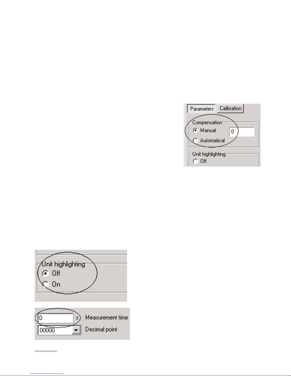
Measurement time -
Measurement averaging time.
W przetworniku P15 gniazdo programatora umieszczone jest wewnątrz obudowy.
W celu przeprogramowania należy zdjąć obudowę i na części czołowej przetwor-
nika umieszczone jest gniazdo typu RJ.
W przetworniku P16 gniazdo programatora umieszczone jest wewnątrz obudowy.
W celu przeprogramowania należy odkręcić 4 wkręty na pokrywie czołowej i zdjąć
obudowę. Na płytce umieszczono 6 pól do podłączenia programatora PD15 z wy-
korzystaniem dołączonej przejściówki RJ-piny.
7.1. Programming of N15 meter
Parameter programming
Compensation - Compensation kind of the meter
working condition changes
Manual compensation:
Introduce the wire resistance value linking the sen-
sor to the meter (in the case of a meter with RTD
sensor) or the value of the ambient temperature (in
case of a meter with a thermocouple).
Automatic compensation:
- In case of a resistance thermometer and resistance measurement, concerns the
compensation of resistance changes of wires linking the sensor with transducer.
It requires a 3-wire line.
- In case of a thermocouple, concerns the compensation of reference junction
temperature changes.
The automatic compensation does not operate in case of a 4000 Ω potentiometer
transmitter or RTD Pt500, Pt1000.
Unit highlighting -
Switching on or off the highlighting of the unit
in the meter (only for meters with a 5-digit
display)
Table des matières
Autres manuels Lumel Carte mère


Manuels Carte mère populaires d'autres marques


Telit Wireless Solutions
Telit Wireless Solutions SL869-3DR Manuel utilisateur

Gigabyte
Gigabyte GA-9IVDT Manuel utilisateur

Texas Instruments
Texas Instruments ADS8372EVM Manuel utilisateur

Commell
Commell MS-C73 Manuel utilisateur

IBT Technologies
IBT Technologies MB860 Manuel utilisateur

Nvidia
Nvidia TEGRA DG-04927-001_V01 Manuel utilisateur


