Louët David 2 Instructions de montage

David
2
Instructions for assembly
Assembly tips and information ........................................................................................................ 1
Instructions for assembly ................................................................................................................2
Warrantee and contact..................................................................................................................17
Version: I_David2_V1_EN


1
Assembly tips and information
Please read all the text of these instructions completely. The pictures may seem clear enough to
assemble the loom; however, the text also contains useful information about operating David 2.
Barrel nuts
To connect parts, barrel nuts are used. These cylinder shaped nuts have a slot on one of the flat
sides. Always insert the barrel nut into the wooden part, so that the side with the slot is visible. The
slot shows the direction of the threaded hole in the nut. With a flat screwdriver you can turn the
barrel nut so that it is positioned properly to catch the bolt. If it is hard to catch the bolt, it usually
helps to turn the barrel nut 180 degrees. If you inserted a barrel nut incorrectly into the wood, a
magnet can be used to remove it.
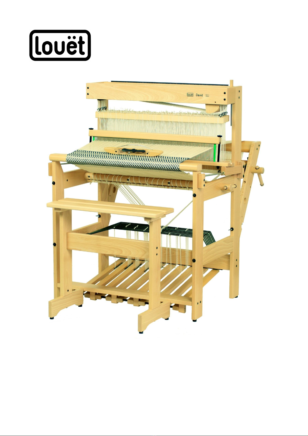
Wood screws
Where wood screws are used, we have predrilled holes in the wood. The screw will cut its own
thread into these holes. The screws are very sharp and will cut their own hole if you miss the
predrilled hole during assembly. If this happens, you will find that after a couple of turns, the screw
will be very difficult to turn. You may even shear the head off of the screw. Also, the parts will be
assembled in the wrong location.
If you have to disassemble and assemble again, makes sure that the wood screw turns in the
same thread again which was cut the first time. Otherwise, after assembling several times, the
thread will be destroyed.
You can find the existing thread by turning the screw counter clock wise, while pushing it into the
wood. When you feel the screw snaps into the thread, turn clock wise. When the screw turns
easily, you know that you have found the thread.
The Texsolv system
Each shaft of the David 2 is provided with one hundred Texsolv heddles (28 cm long). The ties of
these bundles are included and can be used to tie bundles again. A bundle of Texsolv heddles is a
continuous line of 100 heddles folded into a zig zag. Each bundle is fastened in four places. This
makes it easy to pass the shaft bars through the loops of the heddles. If you want to cut the
heddles apart, use a sharp pair of scissors to cut the loops at the top and bottom of the shafts.
Before removing heddles from a shaft, tie them into a bundle. Do not remove the ties from the
bundles, until the heddles have been slipped onto the shaft bars or the loops of the bundles are
inserted by sticks, to protect the heddles from becoming entangled.
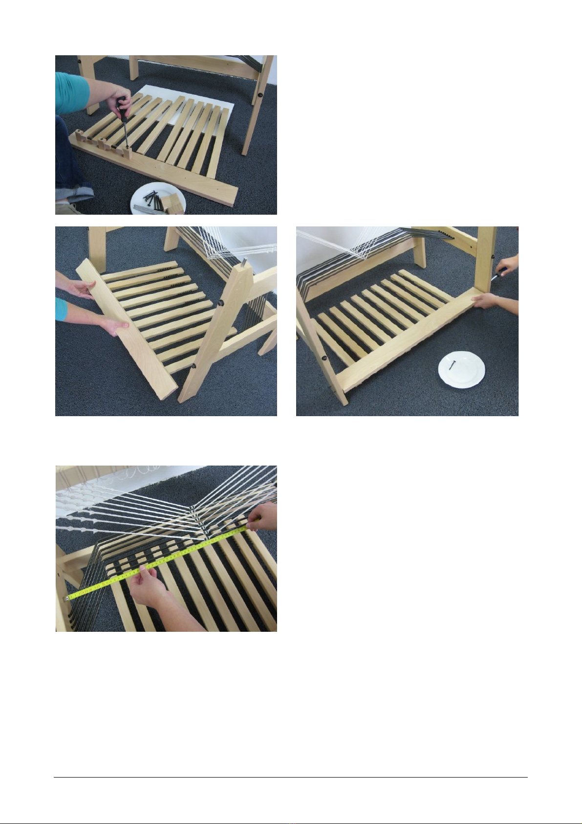
Practically, Texsolv cord consists of two cords, which are connected every 12 mm, forming loops
between them. If needed, the cord should be cut between the two loops. To prevent unraveling, the
ends should be singed with a match or lighter. When we talk about the first or last loop in these
instructions, the loop we mean is the one beside the loop where the cord is cut. The loop that
remains after cutting has no strength and should not be used.
The Texsolv cord is adjustable in length by 12 mm
steps (ca.1/2”), according to the loops. For fine
adjustment, plastic pegs are used, inserted into the
loops of the cord. Each peg through the cord will
shorten it about 1.5 mm (1/16”).
You will not need more than 7 pegs in a cord,
because with 8 pegs the cord becomes one cord
loop shorter and you can just as well shorten the
cord one loop. In hardware bag 3 are 50 spare pegs.

2
Marks
The uprights of the middle part of the loom are marked (A and B) at the location where they should
be connected to the corresponding marked sides of the top side rails. This is to prevent you from
making the mistake of assembling the parts backwards or upside down.
Tools
All hardware parts of Louët products are metric. To facilitate assembly, we have included a metric
wrench 10 mm and a Pozidrive 2 cross head screwdriver (not a Phillips head). A wrench 13 mm is
included with the hardware of the beater.
Accessoires
The following accessories are available for the David 2:
-Bench – height 57 cm (22 3/8”)
-Second warp beam with back beam
-Sectional warping
-Friction brake device for the warp beam
-Flying Dutchman shuttle
Instructions for assembly
We have assembled the castle section of the David loom in the factory.
Slide this assembly out of the box, after you removed the box containing all the parts listed on
next page.
There is a small long box left. This box contains the beater that has to be mounted onto the David
at the end of the assembling.

3
Parts you will find inside the box that came out first (the reed is packed on top of the box):
-foot rail
-back beam
-cloth beam and warp beam
-2 upper side rails L+R
10 treadles
2 beater suspension bars L+R
2 front posts L=R
2 lower side rails L=R (for a David 90 they
are different, see picture below)
-breast beam
-2 lease sticks
-2 apron bars
-16 warp sticks
-shelf
-hardware bags 1, 2, 3 and extra
-ties for the heddles
-reed
-cross head screwdriver pz2
The picture above shows the parts of the David
70.
Into each of the lower side rails, eight nylon
bearings for the lams are inserted.
The picture on the right shows the lower side
rails of the David 90 and the additional lam
squares in which the nylon bearings are
inserted.

4
Open hardware bag 1
The hardware bag contains:
-8 threaded ends m6 X 135 with barrel nut,
washer and cap nut.
-4 screws 5 X 50 mm (these screws you will
need only for a David 90. Sometimes, for
efficiency reasons, they are also included
in the hardware bag of the David 70)
-wrench 10 mm
If your loom is a David 90, use the four 5x50
screws and attach the lam squares to the lower
side rails at the same side where the holes for
the barrel nuts are located.
Position the middle part of the loom with its back to the wall or a table.
The uprights of the middle part are marked
A
and Bat the location where they should be
connected to the corresponding marked sides
of the top side rails.
Unscrew the barrel nuts from the eight
threaded ends, but leave the cap nuts and
washers.
Insert a barrel nut into the top side rail at the
marked end. Remember what you read on the
first page about barrel nuts.

5
Put a threaded end through the hole in the upright. Slide the rail onto the threaded end and push
its wooden dowels into the holes of the upright. Turn the threaded end into the barrel nut, while
positioning the barrel nut, if necessary, using a coin or a screwdriver.
The lower side rails should be mounted the same way, their nylon bearings facing the middle of
the loom. After you mounted all four side rails to the castle section, position the front posts onto
the dowels of the side rails.
Make the connections to the front posts in the
same way you did the connection to the castle
section.
Fasten all eight cap nuts, using the wrench
number 10.
Cut the ties that hold the lams to the back rail and remove the packing paper from the lams.

6
Insert the lams, one by one, with their ends into the nylon bearings, starting with the rear lam:
-Insert one end of the lam into the bearing, while holding the other end of the lam just
underneath the side rail.
-Now bring that other end to its bearing by bending the lam slightly.
-
Push the end into the bearing while you move the lam up and down.
Open hardware bag 2
The hardware bag contains:
6 axle support blocks
6 screws 6 X 70 mm
5 axles 6 X 122 mm
5 nylon bushings 6-8 X 30 mm
4 screws 5 X 50 mm
80 screws 4 X 17 mm
Screw the small screws into the eight holes of
each treadle, so far that the screw heads
protrude approximately 5 mm (3/16”) from the
wood. The thread of the screws should just
disappear into the wood.

7
Assemble the treadles onto the foot rail. The
screw heads on the treadles should point
towards the middle so that the five treadles on
the left side are opposite to the five treadles at
the right side.
Slide two treadles with a nylon bushing in
between on each axle. Use the axle
suspension blocks and the big screws to
assemble these pairs of treadles to the foot
rail.
Put the foot rail with the treadles in between the front posts of the loom and connect these parts
with the four remaining screws.
Check the position of the cords that connect the
lams to the lower shaft bars. The location on the
lams should be exactly in the middle. Replace
the connection to the lams if necessary. Start
with the ones in the front and the back, so the
ones in between can be placed in line.

8
Open hardware bag 3
The hardware bag contains:
2 threaded ends 6 X 135 each with 2 washers and
2 wing nuts
4 screws 5 X 50
8 screws 4 X 15
2 ratchets
2 screws 4,5 X 17 (round head)
2 screw eyes 6
2 screws 3 X 20
2 beam handles with O-ring (If you are going to have
a brake on the warp beam, you only need one)
60 tie-up cords for the treadles
6 beam cords
50 spare pegs to shorten cords
The tie-up cords for the treadles have already
been cut to the correct lengths.
Lead a cord around the lam and insert one end
into the loop at the other end, the one next to
the loop where the cord has been cut.
Pull the cord, so that the loop you made
around the lam is tight.
Hook the other end of the cord to the
corresponding screw head of the treadle.
Tie-up the treadles for the weaving project you
planned, or tie at least each lam to a treadle.
Table des matières
Manuels Tissage populaires d'autres marques

Leclerc Looms
Leclerc Looms COMPACT 4 SHAFTS Manuel utilisateur

Schacht
Schacht CRICKET LOOM Manuel utilisateur

Schacht
Schacht FL3109 Manuel utilisateur

Schacht
Schacht FLATIRON BULKY PLYER FLYER HEAD Guide de démarrage rapide

Leclerc Looms
Leclerc Looms VOYAGEUR Manuel utilisateur

Schacht
Schacht FL3053 Manuel utilisateur


