LEAP Electronics SU-56 Manuel utilisateur

SU-56 Operation Manual
SU-56 Gang Programmer
Operation Manual
-1-

SU-56 Operation Manual
Catalogue
CH1 Product Introduction .........................................................3
CH2 Safety and Precautions......................................................4
CH3 Accessories Notes..............................................................6
3.1 Driver Board Insta ation..................................................6
3.2 Socket Board Insta ation..................................................7
CH4 Hardware and Appearance Description.............................8
4.1 Power.................................................................................8
4.2 USB...................................................................................8
4.3 START Buttom..................................................................8
4.4 Power LED........................................................................8
4.5 Socket Board LED............................................................9
CH5 PC Software Operation Instructions ...............................10
5.1 Software Insta ation Steps.............................................10
5.2 Insta Driver Steps.........................................................10
5.3 Mass Production Software Iinterface (Main)..................11
5.4 Programming UI Description .........................................12
5.5 Mass Production Software Interface (Project)................13
5.6 Mass Production Software Interface (System Option)...14
5.6.1 Log Setting...................................................................14
5.6.2 Se f Test........................................................................15
5.6.3 Information..................................................................16
5.6.4 BIOS Update................................................................17
5.6.5 Auto Run......................................................................18
5.6.6 SD Card........................................................................18
5.6.7 HDCP...........................................................................19
5.6.8 SSD..............................................................................20
5.6.9 PinScan De ay..............................................................20
5.6.10 DateTime Setting.......................................................21
CH6 Simp e Software Operation Steps....................................22
-2-

SU-56 Operation Manual
CH1 Product Introduction
SU-56 is a programming that integrates the existing machine architecture. In
addition to quick y supporting the existing programming components (by
switching or modifying the PCB), it can a so create a dedicated transfer board
for specific components to achieve the diversity of support.
In addition to the rep acement of the Socket modu e board, this machine can
a so be rep aced together with the Driver modu e board be ow. When
supporting some components with specia and comp ex designs, the driver
modu e board can be rep aced to achieve the purpose of support. Save the
comp exity of socket adapter design (reduce rep acement costs).
This type of machine can use a sing e-machine software connection to perform
more comp ex parameter settings for a sing e IC writing and programming
data, and then package it into a project after confirmation.
In mass production, a mass production software with a simp er function and a
simp er interface can be oaded into the project, and mu tip e components can
be programmed at the same time for mass production. This software has no
comp icated operation procedures and cannot change the re evant settings of
the project. The risk of mass production can be minimized.
(The following is only for the function description of the mass-produced
software For the stand-alone software, please refer to the documentation
of Universal IC Writer II )
-3-

SU-56 Operation Manual
CH2 Safety and Precautions
The fo owing safety precautions and safety warnings must be
observed during a operations, maintenance, and repair services. The
company will not be responsible for any unforeseen phenomena
caused by misuse of the instrument without following the
precautions in this manual
1. When rep acing the Socket/Driver modu e board, p ease turn off the
power of the product in advance, carefu y remove the origina
modu e, and then insta the new Socket modu e board. When
insta ing, pay attention to the direction and make the pin headers
a igned before proceeding. Insta ; if there is too much resistance
during insta ation, p ease check again whether there is a wrong
direction or skew, and then restart the product after confirming that
everything is correct.
2. Socket modu e boards are consumab es, depending on the number
of operations of picking and p acing ICs, the habits of personne ,
the c ean iness of the component pin surface, whether the
component packaging meets the standard to erance... and other
factors wi affect the connection between the socket and the IC. In
terms of contact qua ity, when you find that a certain socket modu e
board has a marked increase in the programming defect rate, but
there is no obvious improvement after c eaning the socket, you may
need to consider whether to rep ace the socket modu e board.
3. The machine wi provide power to the modu e board during the
process of IC programming. If the IC is p aced in the wrong
position or the wrong number is se ected, the programming IC may
be damaged.
4. If the programming component is OTP (one-time programming) or
the component has OTP parameter settings, you need to be very
carefu , because the component (or parameter) can on y be
programmed once, and then it cannot be restored through the c ear
function.
5. IC data, batch number, programming process and operating
software are often changed, so when using it, pay attention to
whether the data fi e of the master tape, the set parameters, process
-4-

SU-56 Operation Manual
and software version are a correct.
6. When a new work order or a new IC is aunched for the first time
every day, the IC programmed in the first round must be verified
first to avoid errors in the master tape, fi e, machine or operating
software, resu ting in poor programming. Cause unnecessary osses;
during mass production programming, you must verify whether the
programming IC is norma , inc uding programming program,
component parameter setting, component security protection
setting, specific area setting, bad b ock (NAND F ash) and other
settings.
7. The operator of the machine shou d be trained and designated
personne , and do not a ow untrained personne to operate.
8. During the warranty period, se f-maintenance is prohibited without
the consent of the company.
9. If you find any burning prob ems that cannot be hand ed, p ease
suspend use.
10. The company is wi ing to dea with the customer's burning
prob em, but p ease abide by the above operation statement. If
there is an operation that violates the statement, the company
will not be responsible for the loss caused by machine failure,
IC damage or burning of wrong data any liability
-5-

SU-56 Operation Manual
CH3 Accessories Notes
3.1 Driver Board Insta ation
1. The driver modu e board is fixed on the she mechanism by 4
screws. When removing, p ease oosen it first, remove the screws,
and then push it back to remove.
Before removing, p ease oosen the surrounding screws
2. When assemb ing the new Driver modu e board, p ease confirm
whether there is a mechanism for ocking and supporting above it. If
not, the PCB may be deformed or damaged due to excessive
extrusion during use.
Driver modu e board and screw positions of supporting mechanism
components
3. When assemb ing, just ay it f at, a ign it with the pin header of the
-6-

SU-56 Operation Manual
machine and push it forward, and then ock the screws after
confirming that there is no prob em with the combination.
Before After
3.2 Socket Board Insta ation
1. When the Socket modu e board is removed, it is recommended to ift it up
from the rear, not from either eft or right side, otherwise the pin
header may be damaged.
2. To insta a new modu e board, just a ign and press down.
-7-

SU-56 Operation Manual
CH4 Hardware and Appearance Description
4.1 Power
Use 5V DC power supp y (DC, positive inside and negative outside),
connecting the wrong vo tage and po arity may cause damage to the machine.
4.2 USB
Use a USB B Type connector.
The Cab e attached by our company has the function of ocking it to the she ,
which can avoid the prob em of ooseness caused by co ision and pu ing.
USB cab e ock
ocation
4.3 START Button
It is equiva ent to the START button of the software. After pressing it, the
burning action wi start.
It on y takes effect after the project fi e is oaded.
-8-
SU-56 Operation Manual
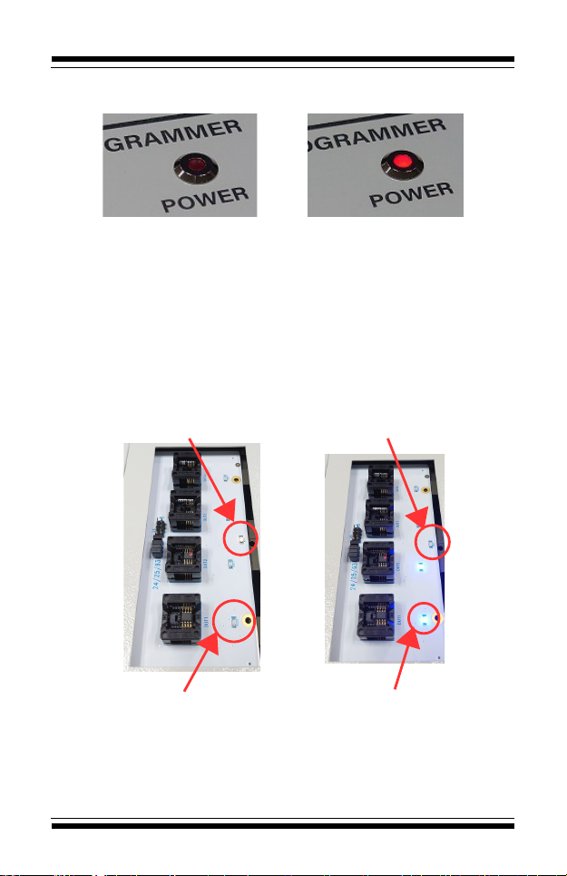
4.4 Power LED
When ight, it means the power is on.
Power OFF Power ON
4.5 Socket Borad LED
WORK LED:Usua y there is on y one, shown in ye ow, it wi be on during
programming, and wi turn off when finished.
PASS LED:Wi increase or decrease according to the number of
sockets(Same number of sockets)。
Bright and not f ashing :The burning is comp eted and the resu t is Pass.
F ashing:The burning is comp eted and the resu t is Fai 。
Dark:The IC has not been p aced or the IC has been removed after
programming.
Programming Programed (Work LED on)
(Work LED off)
Programming Programed
(Pass LED on) (Pass LED off)
-9-

SU-56 Operation Manual
CH5 PC Software Operation Instructions
5.1 Software insta ation steps
5.1.1 Insta Universa IC Writer II.
5.1.2 Insta SU-56.
5.1.3 Insta DataBase。
5.2 Insta software
5.2.1 When insta ing the machine, it is recommended to connect the power
cord and USB cab e first, and then turn on the power of the machine.
5.2.2 After the machine is connected to the PC, there wi be one USB
device (mu tip e devices can be connected at the same time). If the driver needs
to be insta ed for the first connection, p ease point the path to the USBDrv
fo der in the insta ation directory.
5.2.3 Once insta ed (or connected ater) it wi show as "Universa IC
Writer II".
-10-
Table des matières
Autres manuels LEAP Electronics Carte mère

Manuels Carte mère populaires d'autres marques


Telit Wireless Solutions
Telit Wireless Solutions SL869-3DR Manuel utilisateur

Gigabyte
Gigabyte GA-9IVDT Manuel utilisateur

Texas Instruments
Texas Instruments ADS8372EVM Manuel utilisateur

Commell
Commell MS-C73 Manuel utilisateur

IBT Technologies
IBT Technologies MB860 Manuel utilisateur

Nvidia
Nvidia TEGRA DG-04927-001_V01 Manuel utilisateur


