Lanoptik BD1601 Manuel utilisateur

www.lanotpik,com
Digital Comparison Microscope
BD1601
User Manual
LANOPTIK TECHNOLOGIES LTD

User Manual | Digital Comparison Microscope BD1601 www.lanoptik.com
KS065600G4-Ver1.1
Content
CHAPTER 1 NOTES AND SAFETY REQUIREMENTS--------------------------- - 1 -
1.1 CAUTIONS AND NOTES -------------------------------------------------------------------- 1-
CHAPTER 2 REQUIREMENTS FOR WORKING EQUIPMENT--------------- - 2 -
2.1 REQUIREMENTS FOR WORKING EQUIPMENT -------------------------------------------- 2-
CHAPTER 3 PACKING LIST ------------------------------------------------------------ - 3 -
CHAPTER 4 INTRODUCTION TO COMPONENTS------------------------------- - 4 -
4.1 PRODUCT SCHEMATIC AND PART NAME-------------------------------------------------- 4-
4.2PRODUCT PARTS INTRODUCTION -------------------------------------------------------- 5-
4.2.1 Camera ------------------------------------------------------------------------------ - 5 -
4.2.2 Movable Hand Wheel ------------------------------------------------------------- - 5 -
4.2.3 Lens---------------------------------------------------------------------------------- - 6 -
4.2.4 Main light --------------------------------------------------------------------------- - 6 -
4.2.5 Clamp holder ----------------------------------------------------------------------- - 7 -
4.2.6 Rotatable ball head ---------------------------------------------------------------- - 7 -
4.2.7 Adjustable stage-------------------------------------------------------------------- - 8 -
4.2.8 Lifting hand wheel----------------------------------------------------------------- - 8 -
4.2.9 Side light ---------------------------------------------------------------------------- - 9 -
4.2.10 Ports and indicator lights ------------------------------------------------------- - 10 -
4.2.11 Object distance extension ring------------------------------------------------- - 10 -
CHAPTER 5 PRODUCT INSTALLATION METHOD------------------------------ 11 -
5.1 STAGE ASSEMBLY ----------------------------------------------------------------------- - 11 -
5.1.1 Ball head and quick-mount rail assembly ------------------------------------- - 11 -
5.1.2 Quick-mount rail and clamp holder assembly -------------------------------- - 11 -
5.1.3 Stage clips assembly-------------------------------------------------------------- - 12 -
5.1.4 Object distance extension ring assembly -------------------------------------- - 12 -
5.2 CABLE CONNECTION ------------------------------------------------------------------- - 13 -
CHART 6 INSTRUCTIONS--------------------------------------------------------------- 14 -
6.1 START TO USE --------------------------------------------------------------------------- - 14 -
6.2 INSTRUCTIONS -------------------------------------------------------------------------- - 14 -

- 1 -
Chapter 1 Notes and Safety Requirements
1.1 Cautions and Notes
(1) To avoid danger or damage incurred to the lens or lens, do not touch the lens or
sensor directly with your fingers.
(2) To avoid failure or electric shock hazard and so on, do not disassemble or
modify the internal structure of the device.
(3) Do not plug in or unplug the power connection port when hands are wet.
(4) Do not use alcohol and other organic solvents to clean.
(5) If the lens or sensor is dirty or damp, you should better use dry and non-linen
fabric or professional lens tissue to wipe them. To avoid scratches on the
surface, do not touch the lens with your fingers. Wipe the lens or sensor lightly.
(6) The products are not specifically designed for an outdoor use. Do not expose it
to outdoor environment without any protection. Excessive temperature and
humidity will damage the lens. Please avoid using the product under the
following environment: high temperature or high humidity environment, places
with direct sunlight, dirt or vibration and places near heat source.
(7) Please use and store in the following environment:
Operating temperature :0℃~ 40℃
Storage temperature:-20℃~ 60℃
Operating Humidity:30~60%RH
Storage Humidity:10~80%RH
(8) If any foreign matter, water or liquid enter into the device by accident,
disconnect the Power line immediately. Please send it to the maintenance center
and do not use the hair dryer to dry it by yourself.
(9) To prevent microscope from being tripped over or dropped, please put away the
device's connect cable in use or standby.
(10) To avoid electric shock by accident, please power off microscope before you
move your display or equipment.
(11) The cleanliness of the device lens will directly affect clarity degree of contents
from the computer screen during preview. Problems like various circles or spots
on the screen may mostly be incurred by dirt on the lens. When cleaning, please
use professional lens tissue or other professional detergent to clear the dirt on
the lens.
(12) Registered trademark and copyright: Copyright ownership of this product
belongs to Lanoptik Technologies Ltd Without written authorization of this
company, any organizations or individuals shall not photocopy, print, or
translation to another language to any part of this document.
User Manual | Digital Comparison Microscope BD1601 www.lanoptik.com
suppo[email protected]

- 2 -
Chapter 2 Requirements for working equipment
2.1 Requirements for working equipment
●Windows XP SP3、Windows 7(32 or 64 bits)、Windows 8(32 or 64 bits)、
Windows8.1(32 or 64 bits)、Windows10(32 or 64 bits)。
●Quad-core 3GHZ or larger CPU
●100Mbps/1000Mbps network interface
●8G or more memory
●DVD-ROM driver (only needed when installing software)
User Manual | Digital Comparison Microscope BD1601 www.lanoptik.com
suppo[email protected]

- 3 -
Chapter 3 Packing List
1、Microscopebody 2、Rotatable ball head X2 3、Clamp holder X2
4、Quick-mount rail X2 5、Object distance extension ring X2 6、AC/DC power adapter
7、HandscrewX8 8、Installationtools 9、Cable X3
10、StageclipX2 11.Installationdisk
User Manual | Digital Comparison Microscope BD1601 www.lanoptik.com
support@lanoptik.com

- 4 -
Chapter 4 Introduction to components
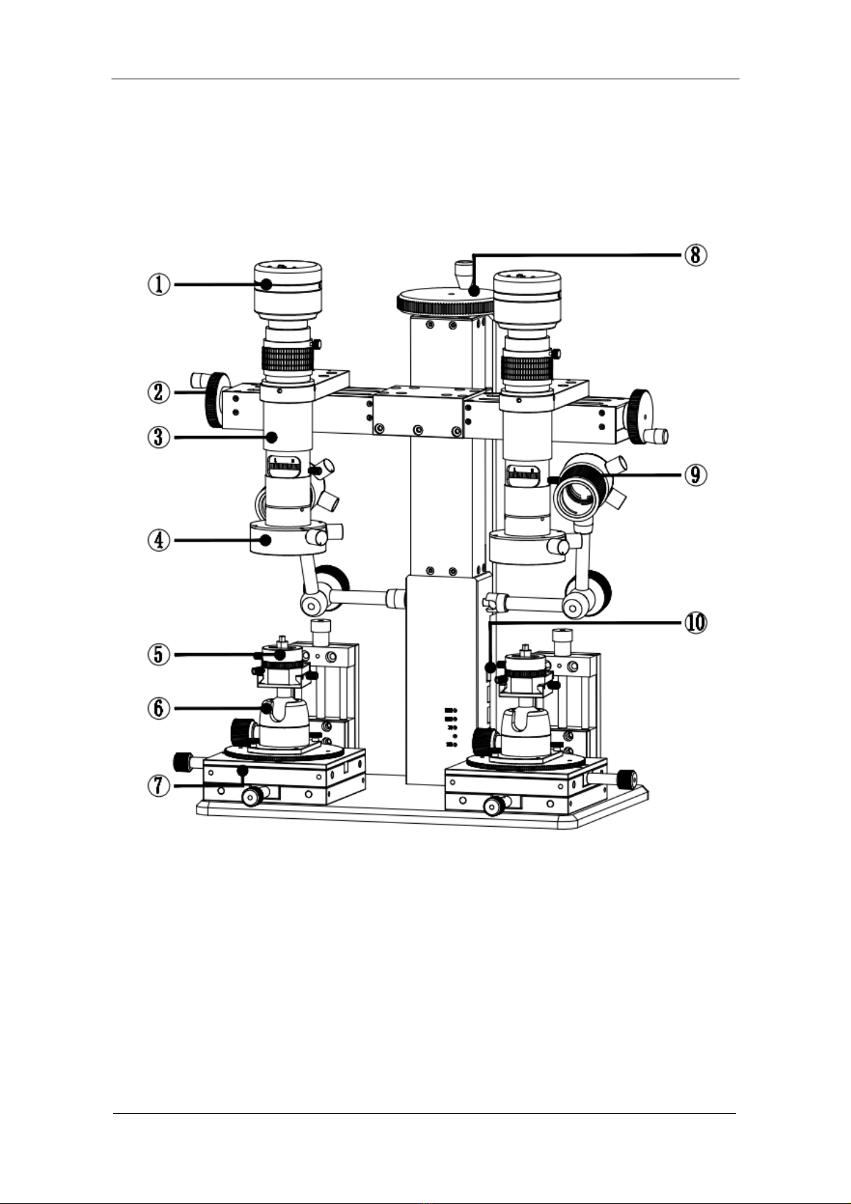
4.1 Product schematic and part name
①Camera ②Movable hand wheel
③Lens ④Main light
⑤Clamp holder ⑥Rotatable ball head
⑦Adjustable stage ⑧Lifting hand wheel
⑨Side light ⑩Ports and Indicator lights
User Manual | Digital Comparison Microscope BD1601 www.lanoptik.com
suppo[email protected]

- 5 -
4. 2 Product parts introduction
4.2.1 Camera
⑪Signal indicator : Blue light flashing, output signal.
⑫Power switch : Turn right (ON), turn on the camera; turn left
(OFF), turn off the camera.
⑬Power indicator : Light does not shine, abnormal power supply;
red Indicator light stays ON, camera is off;
green Indicator light stays ON, camera is on.
⑭Network cable interface : Connect to the CAM interface on the bracket of
main body through the network cable to realize
DC 12V power supply, network 100Mbsp.
4.2.2 Movable Hand Wheel
Rotate clockwise, the lens moves outward; counterclockwise rotation, the lens moves
inward; Travel is 80mm, each turn of the hand wheel moves 1.5mm.
User Manual | Digital Comparison Microscope BD1601 www.lanoptik.com

- 6 -
4.2.3 Lens
○
31 Focal length fixing screw :Focal length fixing screw: After loosening, turn the
Focal length adjustment ring to adjust the focus;
after tightening, fix the magnification at the current
position.
○
32 Focal length adjustment ring :Focal length adjustment ring: Turn this ring to fine
focus the lens.
○
33 Magnification adjustment ring :Magnification adjustment ring: continuous zoom,
turn to the corresponding position, you can get the
corresponding magnification.
○
34 Magnification fixing screw :Magnification fixing screw: After loosening, the
magnification adjustment ring can be rotated to
adjust the magnification; after tightening, the
current magnification can be fixed.
4.2.4 Main light
○
41 Coaxial light control knob :Rotate clockwise to turn on the coaxial light, the brightness of
the lamp is enhanced; counterclockwise rotation, the brightness
of the lamp is weakened, and the coaxial light is turned off.
○
42 Diffuse light control knob :Rotate clockwise to turn on the diffuse light, the brightness of
the lamp is enhanced; counterclockwise rotation, the brightness
of the lamp is weakened, and the diffuse light is turned off.
○
43 Coaxial light :Composed of 13 small angle high-brightness lamp beads.
○
44 Diffuse light :Composed of 40 large angle bright white LED.
○
45 USB cable :Connect to the "5V 1A OUT" interface on the Bracket of main
body to achieve power supply.
User Manual | Digital Comparison Microscope BD1601 www.lanoptik.com

- 7 -
4.2.5 Clamp holder
○
51 Rotation adjustment screw :Loosen the screw, the rotating block can be rotated 360°;
tighten the screw to fix the current rotation angle
○
52 Clamp holder adjustment screw :Turn the screw clockwise to expand the clamp; turn the
screw counterclockwise to tighten the clamp.
○
53 Chuck clamp :By rotating the screw, the slider is contracted to clamp the
object, and the slider expands to support the ring.
○
54 Slider :It can be fastened with the ball head guide rail and rail
block. (Detailed reference: 5.1.1 Ball head and
quick-mount rail assembly)
4.2.6 Rotatable ball head
○
61 Ball head guide rail :Cooperates with the chuck slider for mounting the clamp
holder.
○
62 Guide rail screw :After the clamp holder is installed. Tighten the screw, to secure
the clamp holder to the ball head; loosen the screw, slide or
remove the clamp holder.
○
63 Quick- mount screw hole :The ball head can be quickly mounted to the adjustable stage by
means of a hand screw. (Detailed reference: 5.1.1 Ball head and
quick-mount rail assembly)
○
64 Ball head fastening bolt :After loosening the screw, the position of the ball head guide rail
can be rotated and oscillated; after tightening the screw, the
position of the current ball head guide rail can be fixed.
User Manual | Digital Comparison Microscope BD1601 www.lanoptik.com

- 8 -
4.2.7 Adjustable stage
○
71 Z axis adjustment knob :Rotate clockwise, the stage rises; counterclockwise
rotation, the stage descends; each turn of the knob, the
stage moves 1.5mm, Z-axis travels 50mm.
○
72 X axis adjustment knob :Rotate clockwise, the stage moves to the inside;
counterclockwise rotation, the stage moves outward;
each turn of the knob, the stage moves 2mm, the
X-axis travels 55mm.
○
73 Round platform screw hole :M3 screw hole, the ball head and the guide rail can be
fixed on the adjustable stage by hand screw.
○
74 Round platform :Damping round platform, can rotate 360°; fix each
accessory; level the stage;
○
75 Y axis adjustment knob :Rotate clockwise, the stage moves to the inside;
counterclockwise rotation, the stage moves outward;
the knob moves 2mm per turn, and the X-axis travels
55mm.
4.2.8 Lifting hand wheel
Lifting hand wheel: Turn the knob to drive the microscope to move up and down; turn clockwise to
raise the bracket; counterclockwise to rotate, the bracket is lowered; each turn of the hand wheel,
the lens moves 4mm.
User Manual | Digital Comparison Microscope BD1601 www.lanoptik.com
Autres manuels pour BD1601
1
Table des matières
Autres manuels Lanoptik Microscope
Manuels Microscope populaires d'autres marques

VWR
VWR VisiScope 384 Series Manuel utilisateur

Nikon
Nikon ECLIPSE E200 POL Manuel utilisateur

Leica
Leica DI C800 Manuel

ThermoFisher Scientific
ThermoFisher Scientific Continuµm Manuel utilisateur

ThermoFisher Scientific
ThermoFisher Scientific Continuµm Manuel utilisateur

Olympus
Olympus SZ61 Manuel utilisateur