JGINYUE B85I-PLUS Manuel utilisateur


Contents
Specifications...........................................................................................................1
Overview of Components...................................................................................2
Install CPU & Fan ....................................................................................................3
Install Memory ....................................................................................................... 4
Install Expansion Card ............................................................................................5
Back Panel Connectors ...........................................................................................5
USB 2.0 Port ..................................................................................................... 5
USB 3.0 Port ..................................................................................................... 5
VGA Port ...........................................................................................................5
HDMI Port ........................................................................................................ 6
RJ45 LAN Port ...................................................................................................6
Audio Port ........................................................................................................ 6
PS/2 Port .......................................................................................................... 6
Internal Connectors ................................................................................................7
F_PANEL1 Connector ....................................................................................... 7
SPEAK1 Connector ........................................................................................... 7
JAUD1 Connector ............................................................................................. 7
SATA1~4: SATA 3.0 Connectors.........................................................................8
M.2 Slot ............................................................................................................8
WLAN-1 Slot .....................................................................................................8
JCMOS1: CMOS Discharge ............................................................................... 9
JUSB2: USB 2.0 Connector ............................................................................. 10
FUSB3: USB 3.0 Connector .............................................................................10
BIOS Setup.............................................................................................................. 11
BIOS Setup ............................................................................................................ 11
Enter BIOS Setup .................................................................................................. 12
Reset BIOS ............................................................................................................ 12
—1—
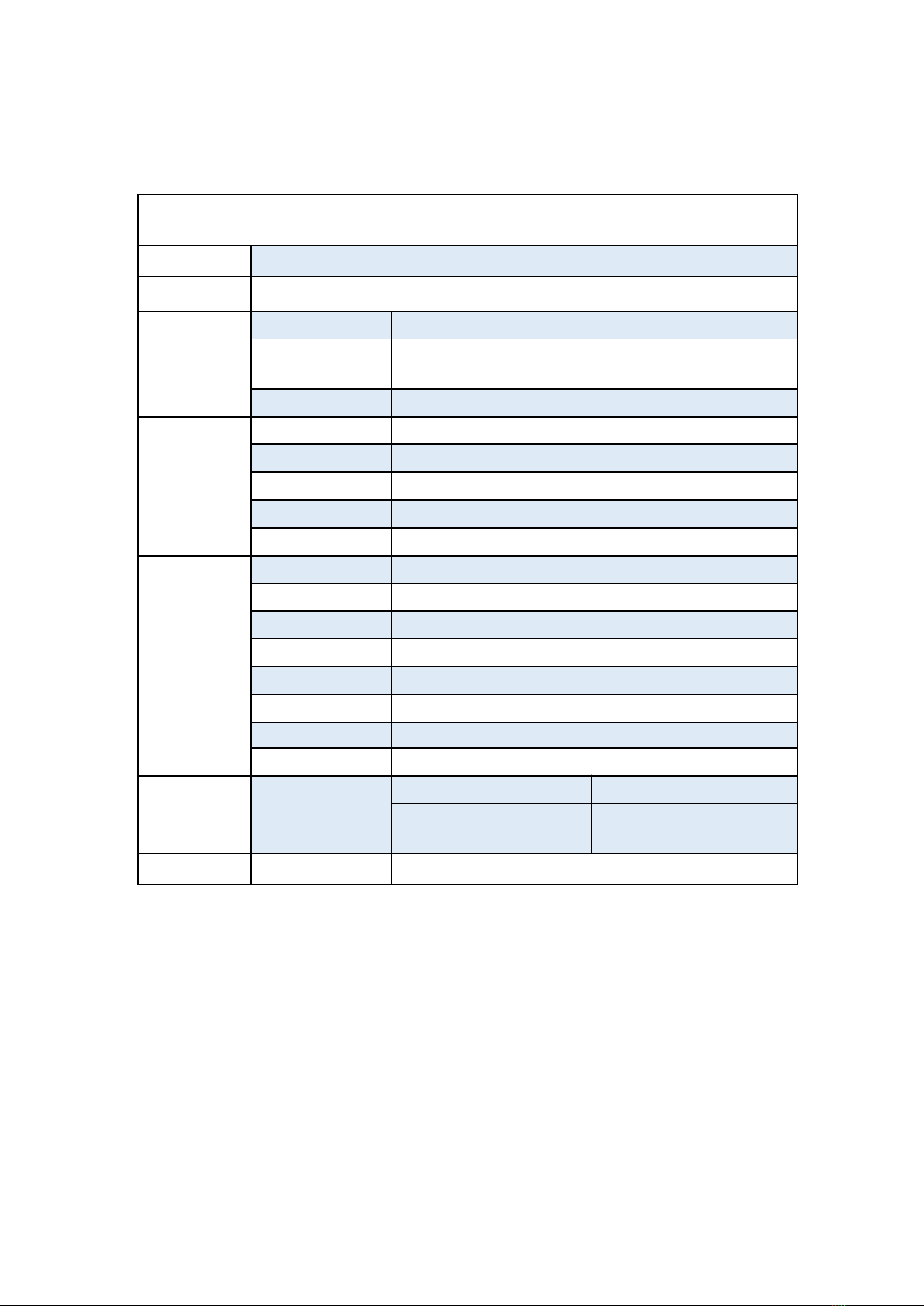
Specifications
B85I-PLUS
Processor
Intel Core/Pentium/Xeon series with LGA1150 pin series processor
Southbridge
B85 Chipset
RAM
Technology
Dual channel DDR3
Maximum
Capacity
16GB (8G*2)
Memory Slot
2 * DDR3
Rear I/O
PS/2
1 * KB/MSInterface
Display Interface
1 * HDMI, 1 * VGA
USB
4 * USB 2.0;2 * USB3.0
Ethernet
1 * Gigabit LAN Card, RTL8111E LAN Card Chip
AUDIO
1 (Mic-in, Line-out、Line-in)
Internal
connector
CFAN
1 * 4PIN
SFAN
1 * 3PIN
ATXPWR Interface
1 * 8PIN Power Socket;1 * 24PIN Power Socket
USB Interface
2 (1 * USB 3.0; 1 * USB 2.0)
M.2
1
SATA Interface
4 (4 * SATA3.0)
JAUDIO
1 * 2x5Pin
PCIe
1 * PCIe x16
Environment
Temperature
Range
Working Environment
Storage Environment
Temperature:0~50°C
Humidity:5%~95%
Temperature: -20~70°C
Humidity: 5%~95%
Physical Size
Size
170mm*170mm
—2—
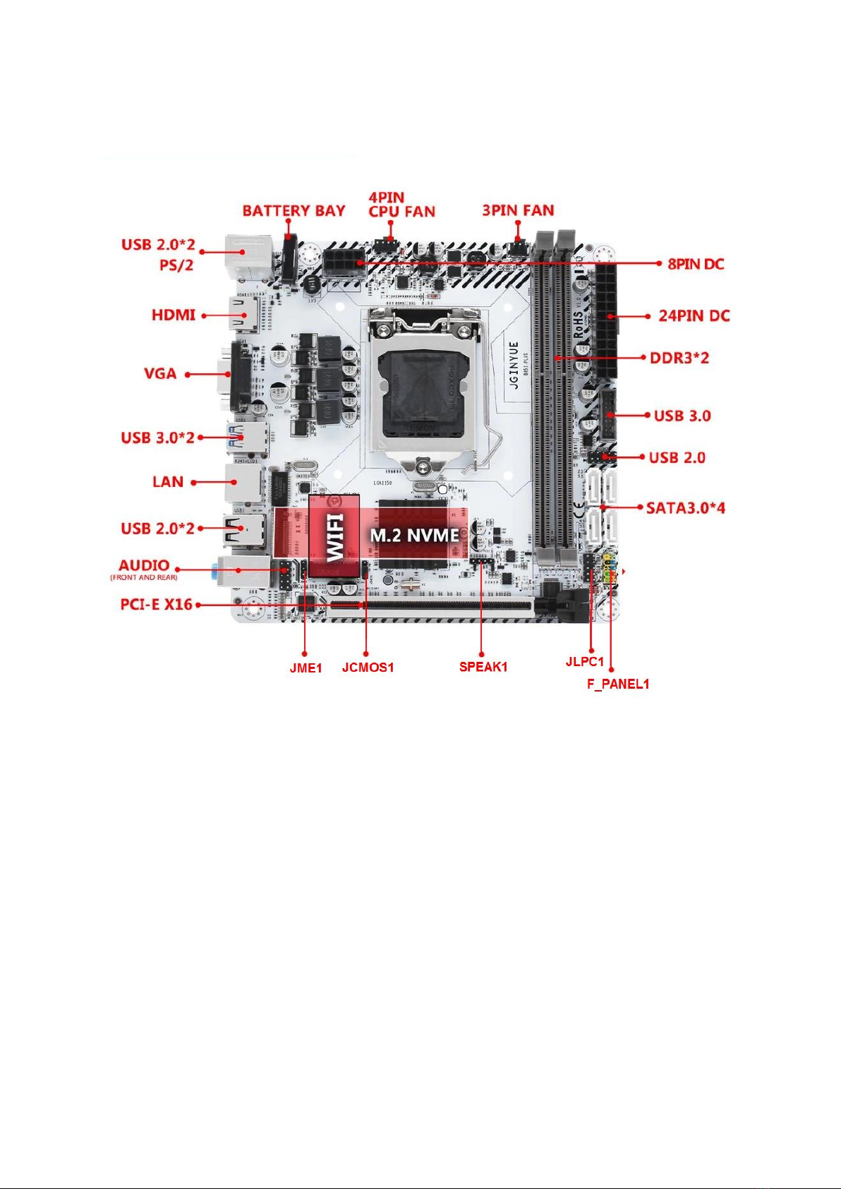
Overview of Components
Package List:
B85I-PLUS Motherboard * 1
SATA cable * 1
I/O blocking * 1
—3—
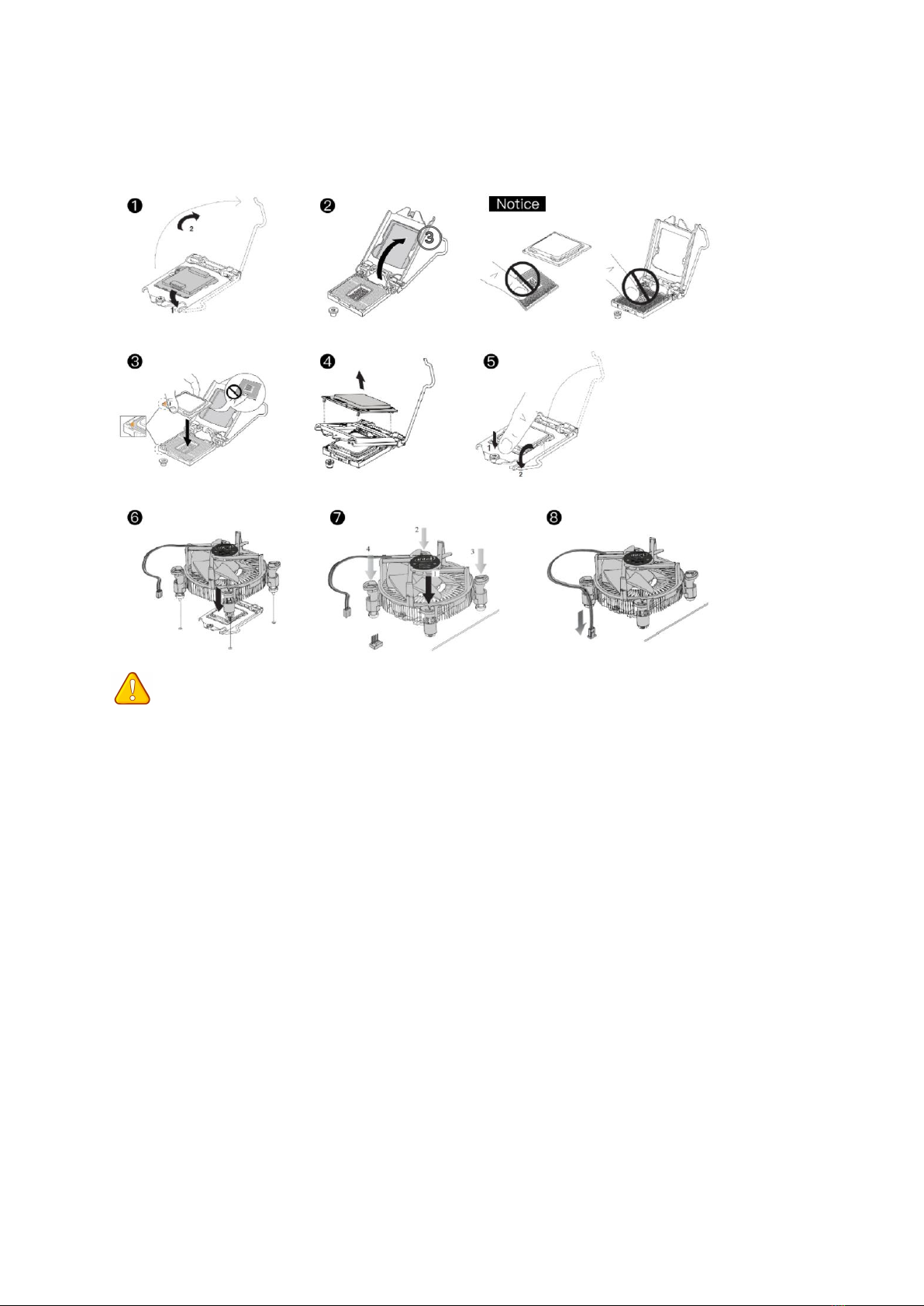
Install CPU & Fan
Please install the CPU into the CPU socket (LGA 1150) as shown below.
Important
• Make sure that the motherboard supports the CPU.
• Always unplug the power cord from the power outlet before installing or removing the
CPU to prevent hardware damage.
• Please retain the CPU protective cap after installing the processor.
• Do not turn on the computer if the CPU cooler is not installed, otherwise overheating and
damage to the CPU may occur.
• Confirm that the CPU heatsink has formed a tight seal with the CPU before booting your
system.
• Apply an even layer of thermal paste (or thermal tape) between the CPU and the heatsink
to enhance heat dissipation.
• Whenever the CPU is not installed, always protect the CPU socket pins by covering the
socket with a plastic cap.
• Locate the pin one of the CPU socket and the CPU. Once the CPU is positioned into its
socket, place one finger down on the middle of the CPU, lowering the locking lever and
latching it into the fully locked position.
• Do not force the CPU into the CPU socket before the CPU socket locking lever is lifted up,
or damage to the CPU and CPU socket may occur.
• Connect the CPU heatsink's 4pin fan power connector to the 4pin CPU fan header on the
motherboard.
—4—
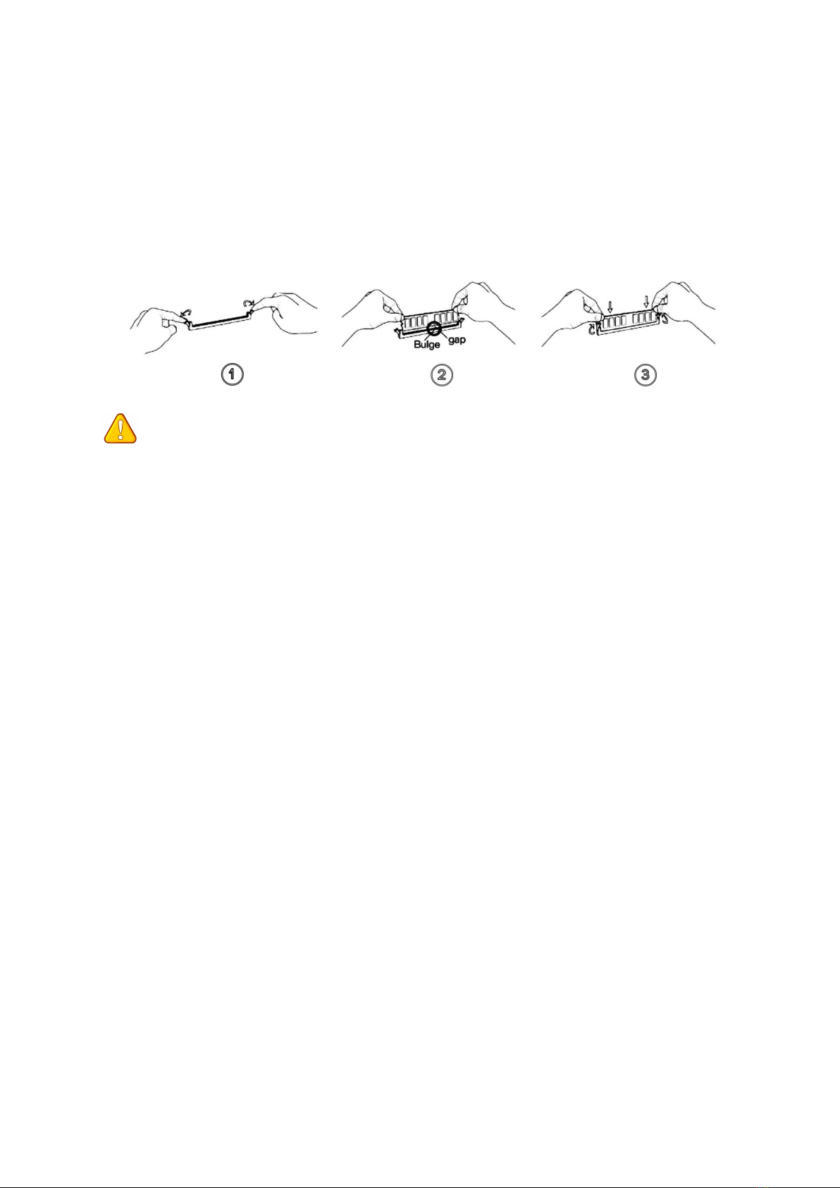
Install Memory
The motherboard provides 2 DDR3 DIMM slots with a maximum capacity of 16GB.
1. Wrench the latches on both sides of the memory slot outwards.
2. Insert the memory into the slot by aligning it with the notch in the slot.
3. Flip the latches on both sides of the slot to lock the memory.
Important
• Make sure that the motherboard supports the memory. It is recommended that memory
of the same capacity, brand, speed, and chips be used.
• Always turn off the computer and unplug the power cord from the power outlet before
installing the memory to prevent hardware damage.
• Memory modules have a foolproof design. A memory module can be installed in only one
direction. If you are unable to insert the memory, switch the direction.
• The stability and compatibility of the installed memory module depend on the installed
CPU and devices when overclocking.
• This motherboard provides two memory sockets and supports Dual Channel Technology.
Dual-Channel mode cannot be enabled if only one memory module is installed.
—5—
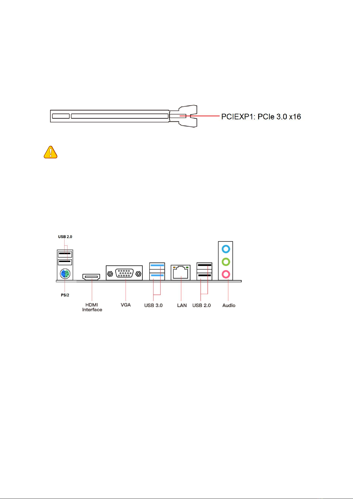
Install Expansion Card
The motherboard provides a PCI Express 3.0 x16 expansion slot.
Place the expansion card in an available PCI Express slot and press the expansion card until it
is fully inserted into the slot.
Important
• When adding or removing expansion cards, always turn off the power supply and unplug
the power supply power cable from the power outlet to prevent hardware damage.
• If the expansion card is not installed correctly, it may cause a short circuit throughout the
metal pins, which could burn out the expansion card or the motherboard.
Back Panel Connectors
USB 2.0 Port
The USB port supports the USB 2.0 specification. Use this port for USB devices.
USB 3.0 Port
The USB 3.0 supports the USB 3.0 specification and is compatible to the USB 2.0
specification. Use this port for USB devices.
VGA Port
VGA (Video Graphics Array) supports analog video signal transmission, high resolution, fast
display rate and rich colors.
—6—
HDMI Port
The HDMI port supports 4K and 1080px. You can use this port to connect your
HDMI-supported monitor.
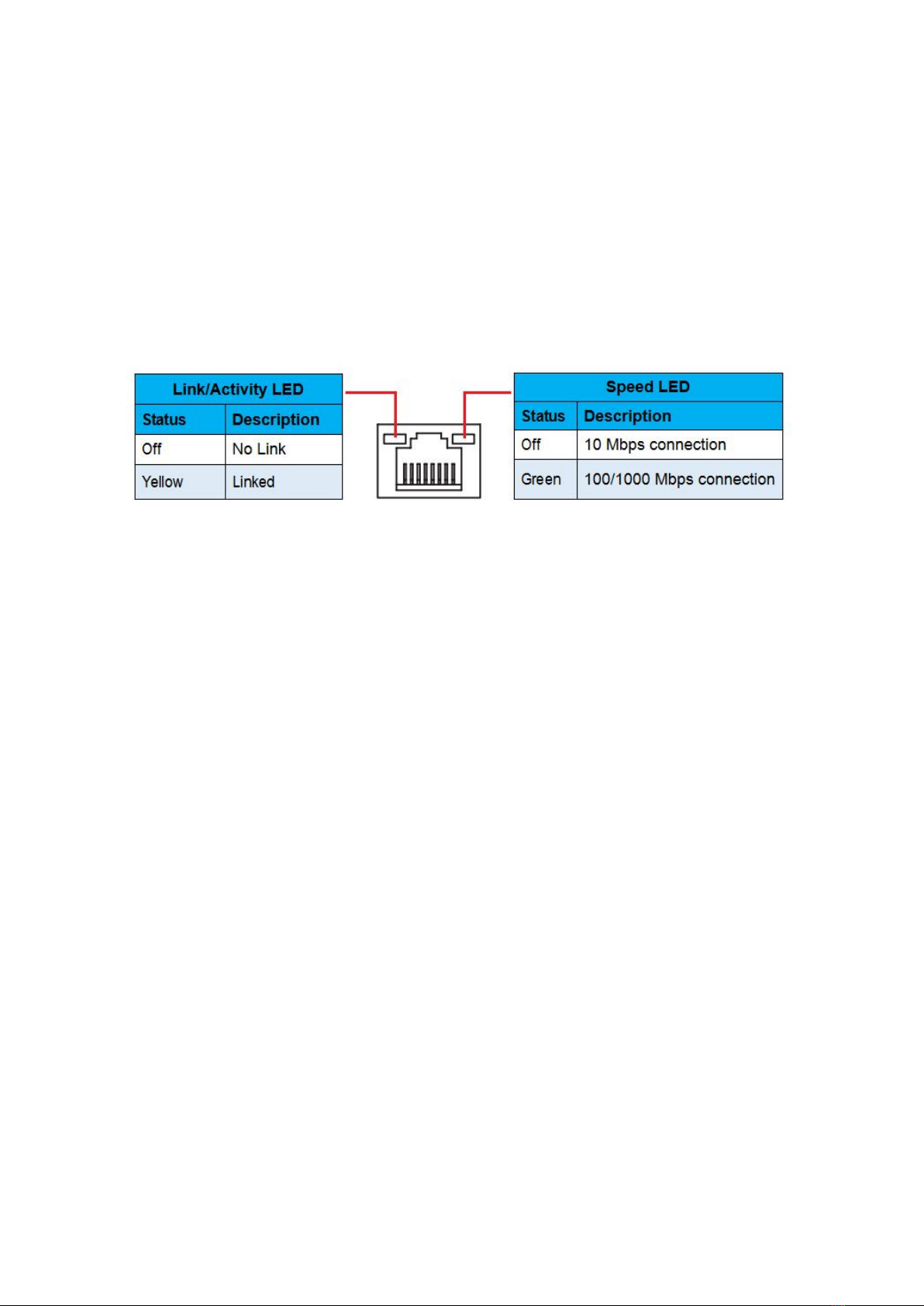
RJ45 LAN Port
The Gigabit Ethernet LAN port provides Internet connection at up to 1000Mbps/s data rate.
The following describes the states of the LAN port LEDs.
Audio Port
Line-in Port
The line in jack. Use this audio jack for line in devices such as an optical drive, walkman, etc.
Line-out Port
The line out jack.
Mic-in Port
The Mic in jack.
PS/2 Port
This PS/2 port can be connected to a keyboard or mouse.
—7—
Internal Connectors
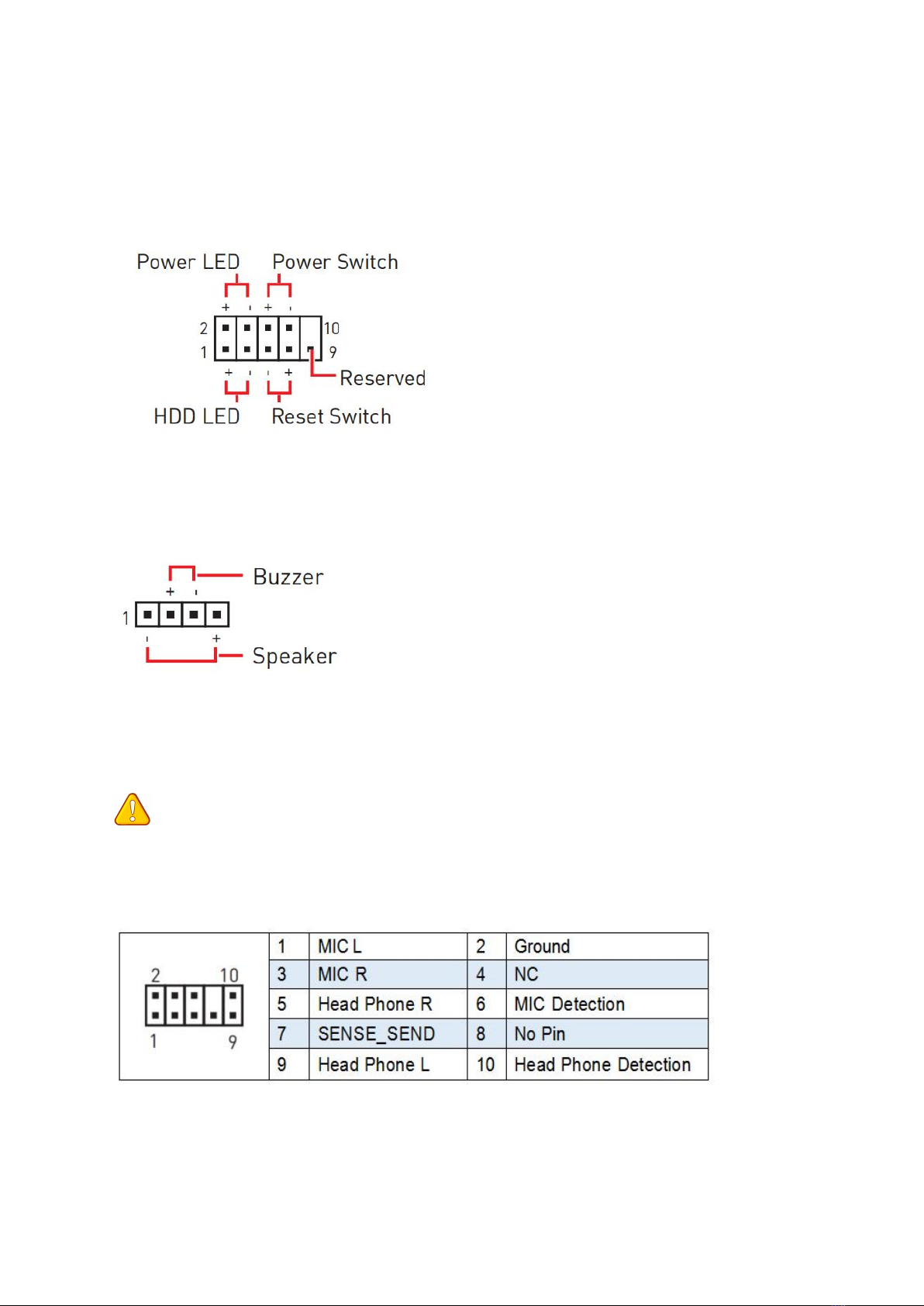
F_PANEL1 Connector
SPEAK1 Connector
JAUD1 Connector
This connector allows you to connect audio jacks on the front panel.
Important
• An incorrect connection between the module connector and the motherboard header will
make the device unable to work or even damage it.
—8—
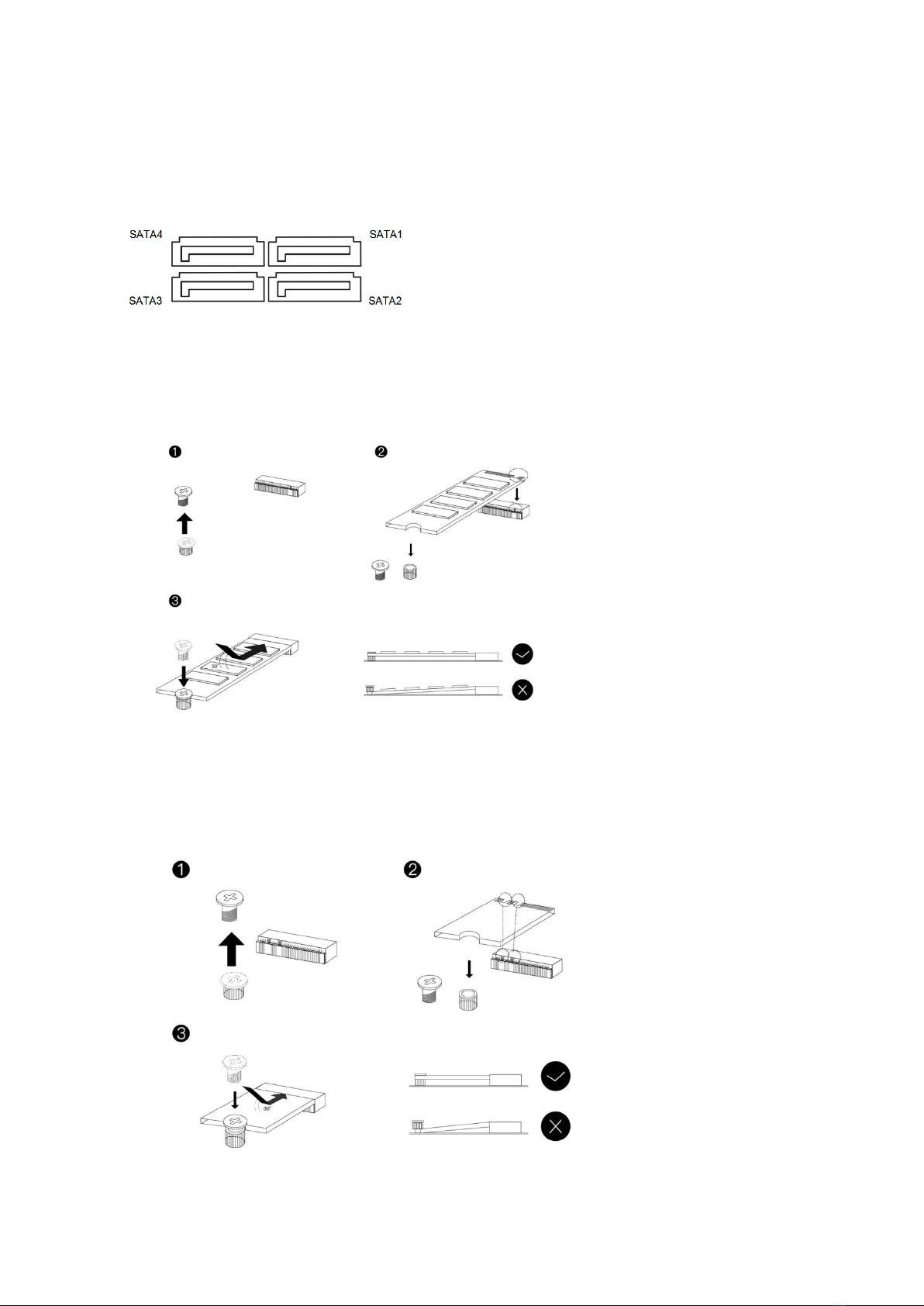
SATA1~4: SATA 3.0 Connectors
These connectors are SATA 6Gb/s interface ports. Each SATA connector supports a single
SATA device.
M.2 Slot
Insert your M.2 SSD into the M.2 slot at a 30-degree angle. Secure the M.2 SSD in place with
the scr ew.
WLAN-1 Slot
The M.2 WiFi interface, which is compatible with WiFi AC standard expansion cards, can be
used after the M.2 WiFi module is installed and the corresponding driver is loaded.
Table des matières
Autres manuels JGINYUE Carte mère


Manuels Carte mère populaires d'autres marques


Telit Wireless Solutions
Telit Wireless Solutions SL869-3DR Manuel utilisateur

Gigabyte
Gigabyte GA-9IVDT Manuel utilisateur

Texas Instruments
Texas Instruments ADS8372EVM Manuel utilisateur

Commell
Commell MS-C73 Manuel utilisateur

IBT Technologies
IBT Technologies MB860 Manuel utilisateur

Nvidia
Nvidia TEGRA DG-04927-001_V01 Manuel utilisateur


