
IRONRIDGE GROUND MOUNT Manuel utilisateur

GROUND MOUNT
INSTALLATION MANUAL

CONTENTS
GROUND MOUNT INSTALLATION MANUAL - 1©2019 IRONRIDGE, INC. VERSION 2.2
DISCLAIMER 1
RATINGS 2
MARKINGS 2
CHECKLIST 3
1. BUILD BASE 4
2. CONNECT SUBSTRUCTURE 4
3. PLACE RAILS 5
4. SECURE LUGS 5
5. SECURE MODULES 6
CAMO 7
ELECTRICAL DIAGRAM 8
DIAGONAL BRACES (OPTIONAL) 9
END CAPS 9
WIRE CLIPS 9
SPLICING CROSS PIPE 10
MICROINVERTER KITS 11
SYSTEMS USING ENPHASE MICROINVERTERS OR SUNPOWER AC MODULES 11
SYSTEMS USING MICROSTORAGE PRODUCTS 12
FRAMELESS MODULE KITS 12
MODULE COMPATIBILITY 13
MODULE COMPATIBILITY 14
MODULE COMPATIBILITY 15
MODULE COMPATIBILITY 16
DISCLAIMER
This manual describes proper installation procedures and provides necessary standards required for product reliability.
Warranty details are available on website. All installers must thoroughly read this manual and have a clear understanding
of the installation procedures prior to installation. Failure to follow these guidelines may result in property damage, bodily
injury or even death.
IT IS THE INSTALLER’S RESPONSIBILITY TO:
• Ensure safe installation of all electrical aspects of the array. All electrical installation and procedures should be
conducted by a licensed and bonded electrician or solar contractor. Routine maintenance of a module or panel shall
not involve breaking or disturbing the bonding path of the system. All work must comply with national, state and local
installation procedures, product and safety standards.
• Comply with all applicable local or national building and re codes, including any that may supersede this manual.
• Ensure all products are appropriate for the installation, environment, and array under the site’s loading conditions.
• Use only IronRidge parts or parts recommended by IronRidge; substituting parts may void any applicable warranty.
• Review the Design Assistant and Certication Letters to conrm design specications.
• Ensure provided information is accurate. Issues resulting from inaccurate information are the installer’s responsibility.
• Validate foundation parameters prior to installation, as a local geotechnical report may be required to assess ground
conditions. We recommend consulting with a local engineer familiar with local regulations and build site requirements,
including soil conditions, terrain and load criteria. All parameters may impact foundation requirements.
• Ensure bare copper grounding wire does not contact aluminum and zinc-plated steel components, to prevent risk of
galvanic corrosion.
• If loose components or loose fasteners are found during periodic inspection, re-tighten immediately. If corrosion is
found, replace affected components immediately.
• Provide an appropriate method of direct-to-earth grounding according to the latest edition of the National Electrical
Code, including NEC 250: Grounding and Bonding, and NEC 690: Solar Photovoltaic Systems.
• Disconnect AC power before servicing or removing modules, AC modules, microinverters and power optimizers.
• Review module manufacturer’s documentation for compatibility and compliance with warranty terms and conditions.
GROUND MOUNT INSTALLATION MANUAL - 2©2019 IRONRIDGE, INC. VERSION 2.2
RATINGS
MARKINGS
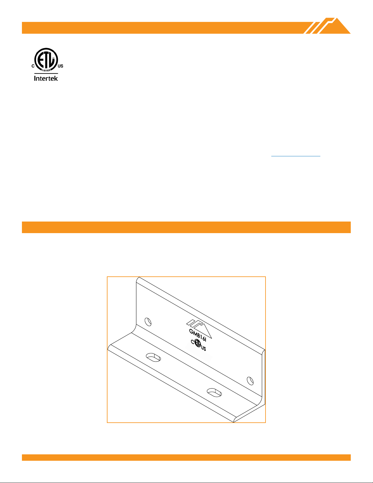
Product markings are located on the system’s Rail
Connectors.
UL 2703 LISTED
• Conforms to STD UL 2703 (2015) Standard for Safety First Edition: Mounting Systems, Mounting Devices, Clamping/
Retention Devices, and Ground Lugs for Use with Flat-Plate Photovoltaic Modules and Panels.
• Certied to CSA STD LTR AE-001-2012 Photovoltaic Module Racking Systems.
• Max Overcurrent Protective Device (OCPD) Rating: 25A
• Max Module Size: 24ft²
• Max Frameless Module Size for Canadian LTR-AE: 19.5 ft²
• CAMO Specic Allowable Design Load Rating: 50 PSF downward, 50 PSF upward, 15 PSF lateral
• LTR AE Canadian Load Rating: 2400 Pa
• System Level Allowable Design Load Rating: meets minimum requirements of the standard (10 PSF downward, 5
PSF upward, 5 PSF lateral). Actual system structural capacity is dened by PE stamped certication letters.
CLASS A SYSTEM FIRE RATING PER UL 2703
• Not Fire Rated
STRUCTURAL CERTIFICATION
• Designed and Certied for Compliance with the International Building Code & ASCE/SEI-7
#5003225
GROUND MOUNT INSTALLATION MANUAL - 3©2019 IRONRIDGE, INC. VERSION 2.2
CHECKLIST
IRONRIDGE COMPONENTSPRE-INSTALLATION
☐Verify module compatibility. See Page 12for info.
☐Purchase 2” or 3” ASTM A53 Grade B Schedule 40
Pipe, galvanized to a min of ASTM A653 G90 or ASTM
A123 G35, or 2.375” or 3.500” Allied Mechanical
Tubing with Gatorshield or FlowCoat Zinc coating
(ASTM A1057).
TOOLS REQUIRED
☐Post Hole Digger or Powered Auger
☐Socket Drive (7/16”, 9/16”, and 1/2” Sockets)
☐Torque Wrenches (0-240 in-lbs and 10-40 ft-lbs)
☐Transit, String Line, or Laser Level
☐3/16” Allen Head
TORQUE VALUES
☐Top Cap Set Screws (3/16” Allen Head)
☐Schedule 40 Grade B Pipe: 20 ft-lbs
☐2.” Allied Mechanical Tubing: 11 ft-lbs
☐3” Allied Mechanical Tubing: 16 ft-lbs
☐Top Cap U-Bolt Nuts (9/16” Socket): 15 ft-lbs
☐Rail Connector Bracket Nuts (9/16” Socket): 21 ft-lbs
☐Rail Connector U-Bolt Nuts (9/16” Socket): 60 in-lbs
☐Grounding Lug Nuts (7/16” Socket): 80 in-lbs
☐Grounding Lug Terminal Screws (7/16 Socket): 20 in-lbs
☐Universal Fastening Objects (7/16” Socket): 80 in-lbs
☐Diagonal Brace Set Screws (1/2” Socket): 15 ft-lbs
☐Diagonal Brace Bolts (1/2” Socket): 40 ft-lbs
☐Microinverter Kit Nuts (7/16” Socket): 80 in-lbs
☐Frameless Module Kit Nuts (7/16” Socket): 80 in-lbs
ÞIf using previous version of: Integrated Grounding Mid Clamps,
Grounding Lug, End Clamps, and Expansion Joints please refer to
Alternate Components Addendum (Version 1.30).
ÞIf installing on a low slope roof please refer to Ground Mount for
Flat Roof Applications Addendum (Version 1.90).
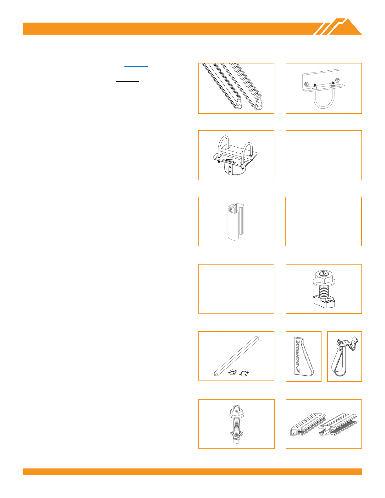
XR100 & XR1000 Rail Rail Connector
Top Cap UFO
Diagonal Brace
Stopper Sleeve
Grounding Lug Microinverter Kit
Frameless Module Kit Frameless End/Mid Clamp
CAMO
End Cap Wire Clip

GROUND MOUNT INSTALLATION MANUAL - 4©2019 IRONRIDGE, INC. VERSION 2.2
1. BUILD BASE
A. MARK LOCATIONS
Establish pier locations. Once grid of pier locations has
been set, verify all angles are square.
ÞSpacing varies with load conditions. Consult engineering specs.
B. POSITION PIERS
Excavate the foundation holes. Insert vertical piers into
foundation holes, and pour in concrete mixture. Ensure
vertical piers are plumb, level, square, and placed in
parallel rows. Level the tops so they are even.
ÞBrace piers until concrete foundation has cured.
ÞIn some cases, cross bracing is required to provide extra support
for piers. If required, install Diagonal Braces at this time.
A. MOUNT TOP CAPS
Mount a Top Cap on each pier. Wait to tighten set screws.
ÞIf using Diagonal Braces, install them prior to Top Caps.
B. LAY CROSS PIPE
Set cross pipes or tubing in Top Cap grooves. Attach with
3/8” U-bolts, ange nuts, at washers, and lock washers.
Torque U-bolts to 15 ft-lbs and align assembly.
Torque Top Cap set screws to 20 ft-lbs for Schedule 40
Grade B Pipe, 11 ft-lbs for 2” Allied Mechanical Tubing,
and 16 ft-lbs for 3” Allied Mechanical Tubing.
ÞTo join more than one section of cross pipe, see Page 10.
2. CONNECT SUBSTRUCTURE
A
B
A
B
Level Tops Vertical Pier
(Schedule 40 Pipe)
Level Ground
90°
U-Bolt
15 ft-lbs
Set Screws
Schedule 40 Grade B Pipe: 20 ft-lbs
2” Allied Tubing: 11 ft-lbs
3” Allied Tubing: 16 ft-lbs
1/3 Depth
Concrete
Foundation
Depth

GROUND MOUNT INSTALLATION MANUAL - 5©2019 IRONRIDGE, INC. VERSION 2.2
3. PLACE RAILS
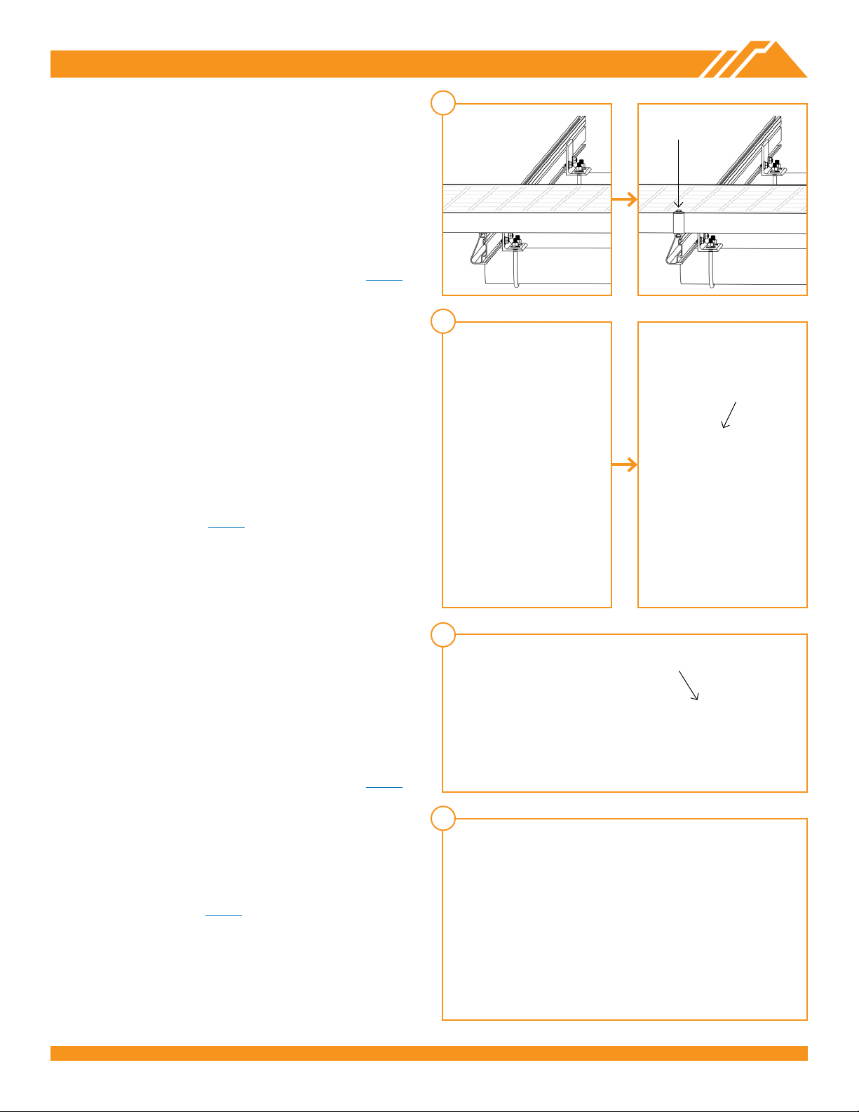
A. ATTACH HARDWARE
On the ground, attach Rail Connector brackets to rail by
sliding 3/8”-16 bonding bolts into side slot. Space out to
match pier spacing. With brackets in place, nger tighten
ange nuts onto bolts.
ÞTape ends of rail, to keep bolts from sliding out while moving.
B. FASTEN CONNECTORS
Center rails on cross pipes, leaving equal distance on
ends. Secure with Rail Connector hardware: 3/8”-16
U-bolts, ange nuts, at washers, and lock washers.
Torque U-bolt nuts to 60 in-lbs and bracket to 21 ft-lbs.
ÞSpacing between rails should align with module manufacturer
recommended clamping locations.
GROUNDING LUGS
Insert T-bolt in top rail slot and torque hex nut to 80 in-
lbs. Install a minimum 10 AWG solid copper or stranded
grounding wire. Torque terminal screw to 20 in-lbs.
ÞOnly one Grounding Lug required per continuous subarray,
regardless of subarray size (Unless frameless modules are used,
see Page 10).
ÞIf using Enphase microinverters or Sunpower AC modules,
Grounding Lugs may not be needed. See Page 11 for more info.
ÞGrounding Lugs can be installed anywhere along the rail and in
either orientation shown.
ÞGrounding Lugs are intended to for use with one solid or stranded
copper wire, conductor size 10-4AWG.
4. SECURE LUGS
A
B
U-Bolt
60 in-lbs
Bracket
21 ft-lbs
Hex Nut
(84 in-lbs)
Terminal Screw
(20 in-lbs)
Hex Nut
(80 in-lbs)
GROUND MOUNT INSTALLATION MANUAL - 6©2019 IRONRIDGE, INC. VERSION 2.2
5. SECURE MODULES
A. SECURE FIRST END
Place rst module in position on rails, a minimum of 1”
from rail ends. Snap Stopper Sleeves onto UFO. Fasten
module to rail using the UFO, ensuring that the UFO is
hooked over the top of the module. Torque to 80 in-lbs.
ÞEnsure rails are square before placing modules.
ÞHold Stopper Sleeves on end while torquing to prevent rotation.
ÞIf using CAMO instead of UFO + Stopper Sleeve, refer to Page 7
for CAMO installation procedure.
B. SECURE NEXT MODULES
Place UFO into each rail, placing them ush against rst
module. Slide second module against UFO. Torque to 80
in-lbs. Repeat for each following module.
ÞWhen reinstalling UFO, move modules a minimum of 1/16” so
UFOs are in contact with a new section of module frame.
ÞWhen UFOs are loosened and re-tightened, ensure UFO T-bolt
bottoms out in rail channel before re-torquing UFO to achieve full
engagement between T-bolt and rail.
ÞIf using Wire Clips, refer to Page 9.
C. SECURE LAST END
Place last module in position on rails, a minimum of 1”
from rail ends. Snap Stopper Sleeves onto UFO. Secure
UFO Clamps on rails, ensuring they are hooked over top
of module. Torque to 80 in-lbs.
ÞHold Stopper Sleeves on end while torquing to prevent rotation.
ÞIf using CAMO instead of UFO + Stopper Sleeve, refer to Page 7
for CAMO installation procedure.
D. REPEAT STEPS
Secure remaining module rows, leaving a minimum 3/8”
gap between rows.
ÞIf using End Caps, refer to Page 9.
A
B
C
D
UFO
80 in-lbs
UFO
80 in-lbs
UFO
80 in-lbs

GROUND MOUNT INSTALLATION MANUAL - 7©2019 IRONRIDGE, INC. VERSION 2.2
CAMO
A. SLIDE INTO RAIL
Slide CAMO into rail channel far enough to clear the
module frame. CAMO requires 6" of clearance from end of
rail.
B. PLACE MODULE
Place module on rails (module cells not shown for clarity).
When installing CAMO the module can overhang the rail
no more than 1/4”.
C. PULL TOWARDS END
Pull CAMO towards rail ends, at 45 degree angle, so the
bonding bolt contacts the module ange edge.
D. SECURE TO FRAME
Rotate handle with an upwards motion until CAMO snaps
into rail channel. Ensure CAMO bonding pins are fully
seated on top of module frame.
FRAME COMPATIBILITY
CAMO has been tested or evaluated with all modules
listed in the Module Compatibility section having frames
within the referenced dimensions. Be sure the specic
module being used meets the dimension requirements.
ÞFor installations with Hanwha Q CELLS modules with 32 mm
frame heights, the maximum ground snow is 45 PSF (33 PSF
module pressure).
ÞCAMO is not compatible with Canadian Solar modules.
A
B
C
D
6" Clearance

GROUND MOUNT INSTALLATION MANUAL - 8©2019 IRONRIDGE, INC. VERSION 2.2
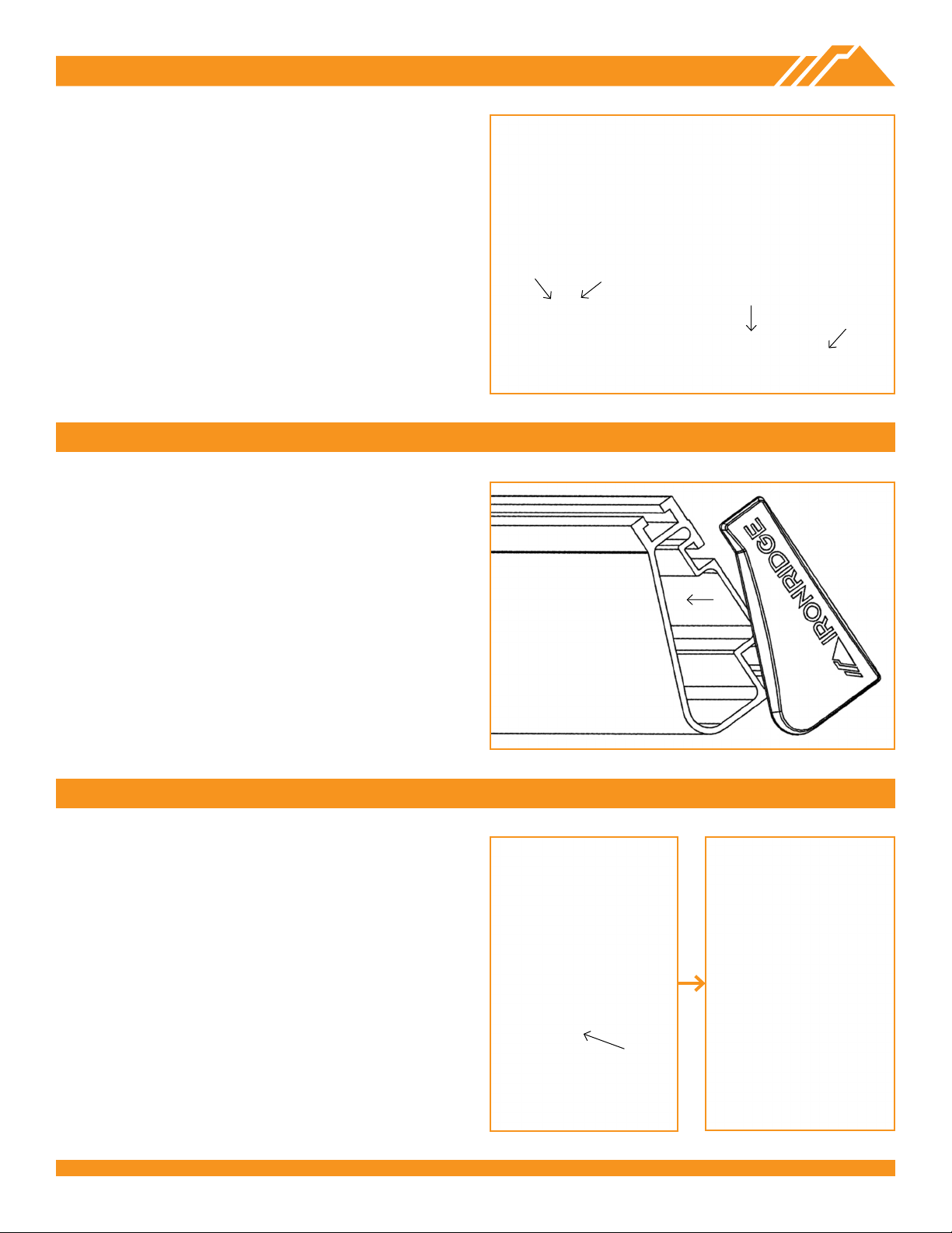
ELECTRICAL DIAGRAM
UFO Clamp Grounding Lug
Min 10 AWG
Copper Wire
Fault Current
Ground Path
Bonding Points Fault Current Ground Path
*Grounding Lugs and wire are not required in systems using
certain Enphase microinverters or certain Sunpower modules.
Equipment grounding is achieved with the Engage cable for
Enphase or the AC module cable system for Sunpower via their
integrated EGC.
*
*
Section View
Plan View
Optional Cross Brace
Only one Grounding Lug required per continuous subarray.
*
Cross Pipe
Rail
Cross Pipe
UFO or
CAMO
GROUND MOUNT INSTALLATION MANUAL - 9©2019 IRONRIDGE, INC. VERSION 2.2
DIAGONAL BRACES (OPTIONAL)
Slide sleeve on north pier 2-3” above the ground (6” max).
Attach Diagonal Brace to sleeve with 1/2” hardware.
Slide second sleeve up on south pier 2-3” below top cap
(6” max). Raise Diagonal Brace to align holes in sleeve
and brace. Attach hardware and raise sleeve to full extent.
Torque Diagonal Brace bolts to 40 ft-lbs. Torque set
screws to 15 ft-lbs.
END CAPS
WIRE CLIPS
End Caps add a completed look and keep debris and
pests from collecting inside rail.
Firmly press End Cap onto rail end.
ÞEnd Caps come in sets of left and right. Check that the proper
amount of each has been provided.
ÞFor open-structure installations, you can use adhesive to secure
the End Caps.
Wire Clips offer a simple wire management solution.
Firmly press Wire Clip into top rail slot. Open clip and
insert electrical wire accordingly. Close clip once complete.
South Pier North Pier
Diagonal Brace
Diagonal Brace Bolts
40 ft-lbs
Set Screws
15 ft-lbs
Sleeve
Press Clip
into Slot
Run Wire
Snap Clip
Closed
Autres manuels pour GROUND MOUNT
1
Table des matières
Autres manuels IRONRIDGE Support et étagère

IRONRIDGE
IRONRIDGE AIRE Manuel utilisateur

IRONRIDGE
IRONRIDGE Standard Rail Roof Mounting Manuel utilisateur

IRONRIDGE
IRONRIDGE XRL Light Rail Manuel utilisateur

IRONRIDGE
IRONRIDGE SGA Addendum Manuel utilisateur

IRONRIDGE
IRONRIDGE Standard Manuel utilisateur

IRONRIDGE
IRONRIDGE QuickMount BUG Manuel utilisateur
Manuels Support et étagère populaires d'autres marques

Salamander
Salamander Acadia AC/W/L400/WH Manuel utilisateur

Fohhn
Fohhn VAT-09 Guide de l'utilisateur

ricoo
ricoo FS0522 Manuel utilisateur

AMSOIL
AMSOIL BMK-22 Guide rapide

Kargo Master
Kargo Master 48220 Manuel utilisateur

Milestone AV Technologies
Milestone AV Technologies SIMPLICITY SLF2 Manuel utilisateur


