Intercoax ECP-2808RM Manuel utilisateur

User Manual
- Hardware -
www.intercoax.com
Ethernet over Coax / UTP Managed Receiving Switch
ECP-2808RM / ECP-2816RM / EUP-2808RM / EUP-2816RM
Rev.3.0

2
Contents
Precaution and Safety Guidelines ...........................................................................................3
1. Product Overview.................................................................................................................4
1.1. Introduction.................................................................................................................................................4
1.2. Features.......................................................................................................................................................4
1.3. Package Contents .....................................................................................................................................4
2. Hardware Installation ...........................................................................................................5
2.1. Front Panel..................................................................................................................................................5
2.2. Rear Panel...................................................................................................................................................6
2.3. LED Indication ............................................................................................................................................7
2.4. Conguration Instruction ..........................................................................................................................8
2.4.1. Prepare devices and materials...............................................................................................................8
2.4.2. Hardware Installation..............................................................................................................................8
2.4.2.1. Rackmount Bracket Installation Guide
2.4.2.2. Rack Mount Instructions
2.4.2.3. Grounding
2.4.3. Joining instruction ................................................................................................................................15
2.4.4. Label the congured network group .....................................................................................................16
2.5. Transmission distance & Bandwidth by distance ................................................................................17
2.5.1. Performance chart................................................................................................................................17
2.6. Typical Installation ...................................................................................................................................19
3. Product Specications.......................................................................................................20
3.1. Technical Specications..........................................................................................................................20
4. Troubleshooting..................................................................................................................21
5. Warranty Policy...................................................................................................................22
6. Regulatory and Certicates...............................................................................................22
7. Customer supports.............................................................................................................22

3
Precaution and Safety Guidelines
• Please install the device following the installation guide.
• Reed all warnings.
• Warning: Do not touch the device and cable with wet hands.
• Warning: Clean this apparatus only with a dry cloth.
• Warning: Please do not put the products on anything electrical conductive (screwdrivers, coins, iron, etc.)
and not put them around water.
• Warning: Do not install near any heat sources such as radiators, heat registers, stoves
or other apparatus that produce heat.
• Warning: Do not use for other purposes.
• Warning: Do not put the signal lines (Coax, UTP) in the same conduit as high voltage wiring
• Do not put any sticker or paint on it.
• Indoor use only.
• Please use only attachments or accessories specied by the manufacturer.
• Unplug the device during a lightning storm or when the device is not used for a long time.
(i.e. Connecting analog camera to BNC connector)
• Do not connect analog cameras to BNC connectors (B-Linx Port) on this devices (ECP Series only)
• Do not connect any IP devices to RJ45 connectors (T-Linx Port) on this devices (EUP Series only)
• When the unit is not working properly, please contact dealer or customer service.
• Please do not disassemble the unit by yourself.
• If this device emits smoke, abnormal noise, or a strange odor, please turn o
the power switch, unplug the AC power cord immediately, and contact dealer or customer service.
The lightning ash with arrowhead symbol within an equilateral triangle, is intended
to alert the user to the presence of uninsulated “dangerous voltage” within
the product’s enclosure that may be of sucient magnitude to constitute a risk
of electric shock to persons.
The exclamation point within an equilateral triangle is intended to alert the user
to the presence of important operating and maintenance (servicing) instructions
in the literature accompanying the product.

Product Overview — 4
1. Product Overview
1.1. Introduction
The All-New Intercoax ECP/EUP-2808RM/2816RM Series is 19” rack mountable managed Long Distance Ethernet
and PoE over Coax/UTP Receiving Switches.
ECP/EUP-2808RM/2816RM series are capable of connecting more than 8/16 ECP Transmitters even with
Daisy-Chain connection and also support PoE powered devices such as IP cameras.
Data rates up to 1Gbps are achievable, making these devices the ideal choice in new or legacy installations where
existing Coax/UTP cable is re-deployed as part of an upgrade fromAnalog to IP cameras.
ECP/EUP-2808RM series have built-in 320 Watt power supply and ECP/EUP-2816RM series have built-in 640 Watt
power supply (*Dual power supply of 320W + 320W for power sharing and redundancy)
PoE up to 60W per port is available.
Intercoax' "ECP Manager", accessible via Web GUI, allows management of all IEEE 1901-HPAV standard devices
connected, and multiple ECP/EUP-2808RM/2816RM devices remotely.
1.2. Features
• Ethernet & PoE transmission over Coax / UTP cable
• Complies to IEEE1901-HPAV standard
• Extended transmission distance up to 2,400m
• PoE/ PoE+/ Extra PoE up to 60W (PoE++) per B-Linx port & T-Linx port
• Total management software, "ECP Manager", via Web GUI
• Friendly Graphic User Interface with EasyView
• Remote Join & Unjoin, Change joining password
• Remote power reset by each port
• Real-time monitoring of power consumption for each port
• Multicast Setting with IGMP Query & Report Generator
• SNMP ready
• VLAN ready
• Port Locking for extra secured network connectivity
• Alarm LED & buzzer and notication on ECP Manager
• Scheduled event reporting and alert reporting to designative users
• Back up & Restore of conguration
• Auto Power Short Protection
• B-Linx & T-Linx Smart Device Detection for safe power transmission
• 320W (8 port) / 640W (16 port) Built-in Power Supply
• Built-in crosstalk canceling technology
• Support multiple conguration (Daisy Chain, Star, Ring, Etc.) on each port
• Gigabit SFP and Copper uplink port
• 19-inch(1U) rack mountable design
1.3. Package Contents
ECP-2816RM
(ECP-2808RM / EUP-2808RM / EUP-2816RM) Bracket Quick Installation
Guide AC Power code

Hardware Installation — 5
2. Hardware Installation
2.1. Front Panel
4
3
56 7 8
5 6 7 81
2
15 6
3
3
4
4
7 8
[EUP-2816RM]
[ECP-2816RM]
[ECP-2808RM]
25 6 7 8
3
4
[EUP-2808RM]
No. Description
1B-Linx Ports (1~8 / 1~16) :
Connect Intercoax ECP Transmitters or IEEE1901-HPAV standard devices by coaxial cable with BNC male
connector.
2T-Linx Ports (1~8 / 1~16) :
Connect Intercoax ECP Transmitters or IEEE1901-HPAV standard devices by UTP cable with RJ45 male
connector.

Hardware Installation — 6
No. Description
3
Smart B-Linx / T-Linx Detection On O :
B–Linx / T-Linx Detection mode On/O switch
- Detection Mode ON: Detects B-Linx & T-Linx devices before supplying power over Coax.
- Detection mode OFF: By-pass detection, classication and power management checks.
[Caution]
Do not connect analog cameras or network devices on BNC or RJ-45 port directly if Smart
B-Linx / T-Linx detection switch is OFF, it may cause a serious damage to the device connected.
4
Join (1-4, 5-8, 9-12, 13-16) :
Hidden button to create new Network group with ECP Transmitters.
- Press the button with a paper clip and hold for 2 seconds for Joining (Create new password).
- Press the button with a paper clip and hold for 15 seconds for Unjoining
(Remove the existing password).
[Note] Please refer to the Network Grouping Software manual, available on Intercoax' Website.
5Buzzer On O :
Move the switch left or right to buzzer sound on or o.
6Factory Reset :
The hidden factory reset button.
Press and hold for 10 seconds the reset button to restore to its original factory settings.
7SFP :
Connect an SFP module for uplink data (1000 Base-FX GBIC slot).
8Link :
Connect an RJ45 Ethernet cable for uplink data (10/100/1000 BaseT).
2.2. Rear Panel
2 1
No. Description
1Power ON/OFF Switch
2Power Connector
The connector is for 100~240V AC power inputs 50Hz/60Hz

Hardware Installation — 7
2.3. LED Indication
2
213 4 6
5
3 4 6
5
2
[EUP-2816RM]
[ECP-2816RM]
[EUP-2808RM]
[ECP-2808RM]
213 4 6
5
3 4 6
5
No. LED
Indication On O Blinking
1B-Linx/T-Linx
(1~8 / 1~16)
• ECP/EUP Transmitter is
connected
• Power over coax / UTP
working properly
• No device connected
on B-Linx / T-Linx port • Short circuit or over current
protection is working
2Join
(1~4 / 5~8,
9~12, 13~16) •• Unjoined ECP device is
connected
• ECP/EUP transmitter linked
properly
• Transmitting Data Via
Coax / UTP
3 Alarm • System boot-up
• Alarm is detected • Device in normal operation • Factory reset is progressing
4 SFP • Transmitting Data • SFP Link is down
• No device connected on
SFP port •
5 LINK • • Uplink (Copper) is down • Transmitting Data
Green: 10/100
Amber: 1000
6 PWR • Power ON • Power OFF •
Hardware Installation — 8
2.4. Conguration Instruction
2.4.1. Prepare devices and materials
• Ethernet over Coax /UTP Receiving Switch (ECP-2808RM, EUP-2808RM, ECP-2816RM, EUP-2816RM)
• ECP-Transmitters (ECP-2701, ECP-8401, ECP-8301, ECP-2601T, etc.)
• EUP-Transmitters (EUP-8401T, EUP-2601T &All ECP-Transmitters with BTE-02)
• RJ-45 patch cord
• Short Coax cable or 4 pairs UTP cable (at least 4 cables for joining)
• Password label (if it is necessary)
• Paper clip (If it is necessary for pressing joining button)
• Network Switch and PC (OS: Window 7 or later)
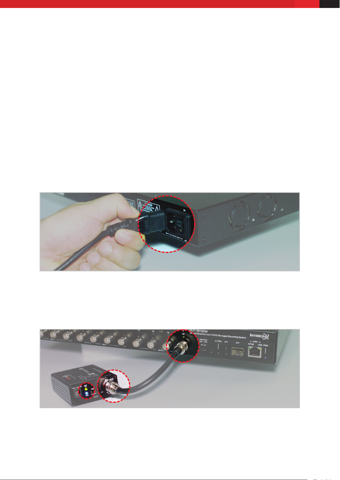
2.4.2. Hardware Installation
1. Apply power to the receiving switch.
2. Use short coax or UTP cables to connect the receiving switch and the ECP/EUP-Transmitters
3. The blue power LED and B-Linx & T-Linx LED of the receiving switch will be ON.
4. The blue power LED of the ECP/EUP-Transmitters will be ON.

Hardware Installation — 9
5. The green join LED of the receiving switch and ECP-Transmitters will blink regularly if both devices are already
joined with same network password.
[Note]
All ECP/EUP products have the same network password as factory default mode to support plug & play
conguration between ECP/EUP Series.
6. If the green Join LED is OFF on both receiving switch and ECP-Transmitter, joining work should be necessary
for network communication.
[Note]
For joining work, Please refer to the Network Grouping Software manual, available on Intercoax' Website.
7. Connect ECP-Transmitters to IP Camera
(IP it is PoE IP Camera, Please select PoE Switch ‘ON’ from ECP Transmitters)
8. Connect the receiving switch to Network switch and PC using RJ45 Patch cord.

Hardware Installation — 10
2.4.2.1. Rackmount Bracket Installation Guide
1. Remove the 3 of factory installed screws from both sides of managed switch and keep these screws as they will
be used to attach the new rack mount brackets. (See Picture 1 & 2)
Picture 1 Picture 2
2. Using these screws, attach the supplied rackmount bracket to the managed switch (Carefully check LEFT and
RIGHT side brackets, see pictures 3 & 4).
Picture 3 Picture 4
2.4.2.2. Rack Mount Instructions
1. Elevated Operating Ambient - If installed in a closed or multi-unit rack assembly, the operating ambient
temperature of the rack environment may be greater than room ambient.
Therefore, consideration should be given to installing the equipment in an environment compatible with the
maximum ambient temperature (Tma) specied by the manufacturer.
2. Reduced Air Flow - Installation of the equipment in a rack should be such that the amount of airow required
for safe operation of the equipment is not compromised.
3. Mechanical Loading - Mounting of the equipment in the rack should be such that a hazardous condition is not
achieved due to uneven mechanical loading.
4. Circuit Overloading - Consideration should be given to the connection of the equipment to the supply circuit
and the eect that overloading of the circuits might have on overcurrent protection and supply wiring.
Autres manuels pour ECP-2808RM
3
Ce manuel convient aux modèles suivants
3
Table des matières
Autres manuels Intercoax Changer

Intercoax
Intercoax ECP-2808RM Manuel utilisateur

Intercoax
Intercoax FLX-1008 Manuel utilisateur

Intercoax
Intercoax HPS-1008 Manuel utilisateur

Intercoax
Intercoax ECP-2808RM Manuel utilisateur

Intercoax
Intercoax HPS-01 Manuel utilisateur

Intercoax
Intercoax ECP-2808RM Manuel utilisateur

Intercoax
Intercoax 2816RM-ECP Manuel utilisateur

Intercoax
Intercoax EUP-2816RM Manuel utilisateur

Intercoax
Intercoax ECP-101T Manuel utilisateur

Intercoax
Intercoax HPS-01 Manuel utilisateur


