
IDE DK85R Series Manuel utilisateur

IDE Solid State Disk
Rev. A.6 Nov. 2008
Turbo II+ 2.5" IDE Solid State Disk
DK85R Series
081124001064
IDE Solid State Disk
Rev. A.6 Nov. 2008
Table of Contents
1. Product Description ..................................................................................................................1
1.1 Product Overview ............................................................................................................................ 1
1.2 Product Features............................................................................................................................. 1
1.3 System Requirement ...................................................................................................................... 1
2. Specification ..............................................................................................................................2
2.1 Physical Specifications ................................................................................................................... 2
2.2 Electronic Specifications ................................................................................................................ 4
2.3 Performance Specifications ........................................................................................................... 5
2.4 Environmental Specifications ........................................................................................................ 6
2.5 Reliability Specifications................................................................................................................. 6
2.6 Compliance Specifications............................................................................................................. 6
3. Function......................................................................................................................................7
3.1 Pin Signal Assignment.................................................................................................................... 7
3.2 Support ATA Commands ................................................................................................................ 8
3.3 Firmware Upgrade ........................................................................................................................ 27
4. Installation................................................................................................................................28
4.1 Installation ...................................................................................................................................... 28
4.2 Partition........................................................................................................................................... 28
4.3 Format............................................................................................................................................. 30
5. Troubleshooting.......................................................................................................................31
5.1 BIOS can not identify 2.5” IDE SSD........................................................................................... 31
5.2 2.5” IDE SSD can not boot the system...................................................................................... 31
6. Ordering Information...............................................................................................................31
7. Contact Information.................................................................................................................32
IDE Solid State Disk
Rev. A.6 Nov. 2008
List of Figures
Figure 1: 2.5˝IDE SSD Overlook Diagram ...............................................................................2
Figure 2: 2.5” IDE SSD Dimensions .........................................................................................3
Figure 3: 2.5˝IDE SSD Block Diagram.....................................................................................4
Figure 4: IDE Connector Pin Assignment .................................................................................7

IDE Solid State Disk
Rev. A.6 Nov. 2008
List of Tables
Table 1: 2.5” IDE SSD Physical Dimension (Type 1) ................................................................3
Table 2: IDE connector pin definitions ......................................................................................7
Table 3: ATA Command Set ......................................................................................................8
Table 4: Diagnostic Codes........................................................................................................9
Table 5: Identify Device Information........................................................................................10
Table 6: Feature Supported ....................................................................................................22
Table 7: Transfer mode values................................................................................................23
Table 8: Advanced power management levels........................................................................23
Table 9: Turbo 2.5” IDE SSD Ordering Information.................................................................31
Copyright Information
Copyright © 2008, CoreSolid Storage Corporation. All rights reserved.
The information and specifications provided in this document should be used for comparative analysis and
reference purposes. The content of this document is subject to change without prior notice.

IDE Solid State Disk
Rev. A.6 1/32 Nov. 2008
1. Product Description
1.1 Product Overview
CoreSolid Storage designs IDE Solid State Disk(SSD) in PQI brand name is the storage device based on NAND flash
memory technology. This product complies ATA standard interface and is suitable for data storage media and code
storage device for embedded system and boot disk. By using 2.5˝IDE SSD, it is possible to operate good performance
for the systems, which have IDE(ATA) Interface.
With small form factor, the applicable appliance can add or install IDE storage device on its Mother Board or Complete
set.
zApplication Fields;
Industrial PC and Thin Client
Game and Telecommunication Machine
Ticketing, Examining, testing machine
Army, Health and Production Equipment and Machine
1.2 Product Features
zSmall form factor with IDE Standard Interface connector
zMemory Capacities: 8GBytes ~ 64GBytes
zHigh performance and reliability
zNoiseless and stable installation to system
zOperating voltage 5.0V operation
zStandard ATA Interface
zOperating as Boot Disk
zData Storage Device to 64GBytes
zCode Storage Device for Embeded Operating System
1.3 System Requirement
- The Host system which is connected to 2.5˝IDE SSD should meet system requirements at minimum;
1.3.1 Power Requirement
zVoltage: DC +5.0V ± 10%
1.3.2 Operating System
zWindows 2000/XP/Vista
zLinux
zDOS
zWinXP Embedded
zWinCE
1.3.3 Interface
zStandard IDE(ATA) Interface

IDE Solid State Disk
Rev. A.6 2/32 Nov. 2008
2. Specification
2.1 Physical Specifications
2.1.1 Overlook
The overlook views of 2.5˝IDE SSD are illustrated in Figure 1.
<Front View> <Rear View>
Figure 1: 2.5˝IDE SSD Overlook Diagram
IDE Solid State Disk
Rev. A.6 3/32 Nov. 2008
2.1.2 Dimension
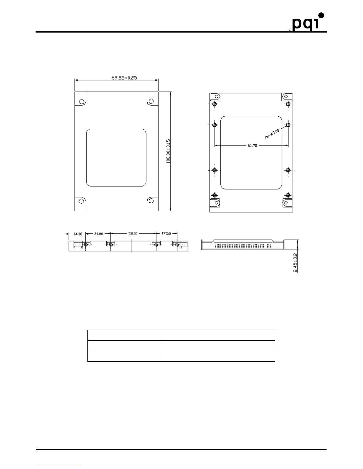
The Dimensions of 2.5˝IDE SSD are illustrated in Figure 2 and described in Table 1.
Figure 2: 2.5” IDE SSD Dimensions
Table 1: 2.5” IDE SSD Physical Dimension (Type 1)
Length 100 ± 0.15 mm
Width 69.85 ± 0.25 mm
Thickness 8.45 ± 0.2mm
2.1.3 Weight
zWeight: 126g

IDE Solid State Disk
Rev. A.6 4/32 Nov. 2008
2.2 Electronic Specifications
2.2.1 Product Definition
2.5˝IDE SSD is designed to operate and work as Data or Code Storage device by NAND Flash Memory and its
Controller through Standard ATA Interface to Host Systems.
DASP , PDIAG
FLASH
Controller
DATA
BUFFER
DATA
FLASH
ARRAY
Regulator
DMARQ
DMACK
Master/Slave
External Option
IORDY
INTRQ
DIOR
DIOW
DA0 to DA2
RESET
CS0, CS1
DD0 to DD15
Hvcc
Vcc
Interface
ATA(IDE) Flash memory bus
X`tal
Control signal
Figure 3: 2.5˝IDE SSD Block Diagram
2.2.2 Operating Voltage
zVoltage DC +5.0V ± 10%
2.2.3 Capacity and Block Size information
zCapacity: 8GBytes ~ 64GBytes
zSector Size: 512Bytes

IDE Solid State Disk
Rev. A.6 5/32 Nov. 2008
2.2.4 Power Consumption
zDC Information
Voltage Testing Item Read Sector Current Write Sector Current Stand-By Current
Maximize/Peak Current 97.2mA 100.4mA 70.7mA
Normal Current 97mA 99.7mA 70.5mA
5V
Watts 486mW 502mW 353.5mW
※
Testing Platform;
- Mother-Board: GA-K8U-939, CPU: k8 2.0G, System Memory: DDR 256MB,
- Operating System: DOS 6.22, Test Program: RWALL10 & DOMSV31
- Test sample : IDE 2.5” SSD 64GB
2.3 Performance Specifications
2.3.1 Modes
zPIO mode 6
zMW DMA 4
zUltra DMA 5
2.3.2 Access Time
z2.5˝IDE SSD’s maximum access time is about 0.25msec.
※
Testing Platform
- Testing S/W: QBench, Testing OS: DOS, Data: 1sector (512Bytes)
- Testing base: Time required Between Host to Device
2.3.3 Seek Time
z2.5˝IDE SSD has no seek time by being based on Flash Memory technology.
2.3.4 Mount Time
The Mount Time for initializing and mounting 2.5˝IDE SSD is different by depending on Operating System and testing
Platform.
2.3.5 Data Transfer Time
zSequential Read: Up to 61 MB/sec
zSequential Write: Up to 33 MB/sec
※
Test Platform: GIGA 8I945GME Intel:945+ICH7 3.0GHz DDR:400
- Testing Software: HD Bench 3.4 Testing OS: Windows XP
Notice: The value is various bases on the testing platform.
2.3.6 Data Retention
z10years without requiring power support
Notice: The Value of Data Retention is various bases on the type and manufacturer of Flash Memory
2.3.7 Wear-leveling
zDynamic Wear-Leveling for same level of Write/Erase Cycle
2.3.8 Bad Block Management
zThe Bad Blocks of Flash Memory will be replaced into new ones by controller.
2.3.9 Read/Write Cycle
zRead/ Write 2,000,000 times

IDE Solid State Disk
Rev. A.6 6/32 Nov. 2008
2.4 Environmental Specifications
2.4.1 Temperature
zOperating Temperature: 0ºC to +70ºC
zNon-Operating Temperature: -40ºC to +85ºC
2.4.2 Humidity
zOperating Humidity: 10% to 95%
zNon-Operating Humidity: 10% to 95% (with no condensation relative humidity)
2.4.3 Vibration
zRandom Vibration (Non-Operation): 10~2000 Hz @ 6Grms
zRandom Vibration (Operating): 10~500 Hz@ 3 Grms
2.4.4 Altitude
z30,000ft
2.5 Reliability Specifications
2.5.1 ECC/EDC (Error Correction Code/Error Detection Code)
z1bytes data by 128bytes will be corrected.
2.5.2 Read and Write/Erase Cycle
zRead: No Limitation
zWrite/Erase: 2,000,000 times
Notice: The Value of Write/Erase Cycle is various bases on the type and manufacturer of Flash Memory.
2.5.3 MTBF (Mean Time Between Failure)
z2,000,000 hours
2.6 Compliance Specifications
zCE
zFCC
Notice: Please contact your closest CSS or PQI’s office for other certificate information.
Table des matières
Manuels Matériel informatique populaires d'autres marques

EMC2
EMC2 VNX Series Manuel du propriétaire

Panasonic
Panasonic DV0PM20105 Manuel utilisateur

Mitsubishi Electric
Mitsubishi Electric Q81BD-J61BT11 Manuel utilisateur

Gigabyte
Gigabyte B660M DS3H AX DDR4 Manuel utilisateur

Raidon
Raidon iT2300 Manuel utilisateur

National Instruments
National Instruments PXI-8186 Manuel utilisateur


