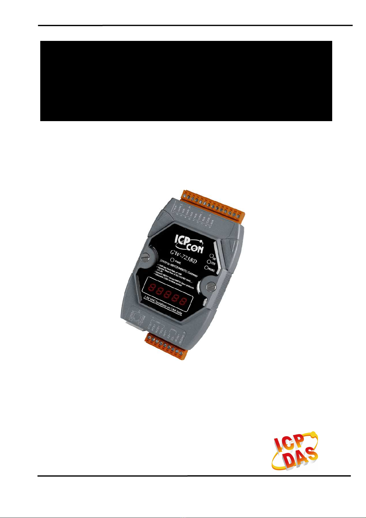
ICPDAS GW-7238D Manuel utilisateur

GW-7238D J1939 to MBTCP Server / MBRTU Slave Gateway User’s Manual (Ver.1.0, Nov. 2011) --- 1
User’s Manual
www.icpdas.com
GW-7238D
J1939 to Modbus TCP Server / RTU
Sl
ave Gateway

GW-7238D J1939 to MBTCP Server / MBRTU Slave Gateway User’s Manual (Ver.1.0, Nov. 2011) --- 2
Warranty
All products manufactured by ICP DAS are under warranty regarding
defective materials for a period of one year from the date of delivery to the
original purchaser.
Warning
ICP DAS assumes no liability for damages resulting from the use of
this product. ICP DAS reserves the right to change this manual at any time
without notice. The information furnished by ICP DAS is believed to be
accurate and reliable. However, no responsibility is assumed by ICP DAS
for its use, or for any infringements of patents or other rights of third
parties resulting from its use.
Copyright
Copyright 2011 by ICP DAS. All rights are reserved.
Trademark
The names used for identification only may be registered trademarks
of their respective companies.
Document Revision
Version Author Date Description of changes
1.0 T.H. 2010-11-12 First Release Revision

GW-7238D J1939 to MBTCP Server / MBRTU Slave Gateway User’s Manual (Ver.1.0, Nov. 2011) --- 3
Table of Contents
1.
Introduction.......................................................................................5
1.1 Mode of operation.............................................................................. 5
1.2 Features............................................................................................. 6
1.3 Specifications..................................................................................... 6
2.
Hardware ...........................................................................................8
2.1 Block Diagram.................................................................................... 8
2.2 Pin Assignment.................................................................................. 9
2.2.1 RS-232 & RS-485 & Power supply Interface.................................... 9
2.2.2 CAN bus Interface............................................................................ 9
2.2.3 Ethernet Connect........................................................................... 10
2.3 Hardware Connection .......................................................................11
2.3.1 CAN port connection.......................................................................11
2.3.2 Serial / Ethernet / Power port connection....................................... 12
2.4 Terminator Resistor Settings............................................................ 12
2.5 Init / Normal Dip-switch.................................................................... 14
2.5.1 Firmware Update Mode.................................................................. 14
2.5.2 Firmware Operation Mode.............................................................. 16
2.6 LED Indication.................................................................................. 16
2.7 5-digits 7-segment LED Displays..................................................... 18
3.
Software...........................................................................................21
3.1 Configuration Tool – GW-7238D Utility............................................. 21
3.2 GW-7238D Utility ............................................................................. 22
3.2.1 Connection Screen......................................................................... 22
3.2.2 Main Screen................................................................................... 23
4.
Communication Network................................................................31
4.1 Modbus Network.............................................................................. 31
4.1.1 Supported Modbus Functions ........................................................ 31
4.1.2 Modbus Address ............................................................................ 31
4.2 J1939 Network................................................................................. 33
4.2.1 Communication Methods................................................................ 33
4.2.2 Parameter Groups.......................................................................... 33
4.2.3 Suspect Parameter Number (SPN)................................................ 34
4.2.4 J1939 Message Transmission........................................................ 35
4.2.5 J1939 Receiving Messages ........................................................... 36
4.2.6 Transport Protocol for Large Messages......................................... 36
5.
Application ......................................................................................37
5.1 Hardware Installation ....................................................................... 37

GW-7238D J1939 to MBTCP Server / MBRTU Slave Gateway User’s Manual (Ver.1.0, Nov. 2011) --- 4
5.2 GW-7238D Utility Configuration....................................................... 40
5.2.1 Modbus Network Configuration...................................................... 40
5.2.2 J1939 Network Configuration......................................................... 40
5.2.3 J1939 I/O Configuration ................................................................. 41
5.2.4 Upload Parameter to the GW-7238D ............................................. 43
5.3 Modbus Communication – Modbus RTU ......................................... 44
5.4 Modbus Communication – Modbus TCP.......................................... 47
6.
Troubleshooting..............................................................................51

GW-7238D J1939 to MBTCP Server / MBRTU Slave Gateway User’s Manual (Ver.1.0, Nov. 2011) --- 5
1. Introduction
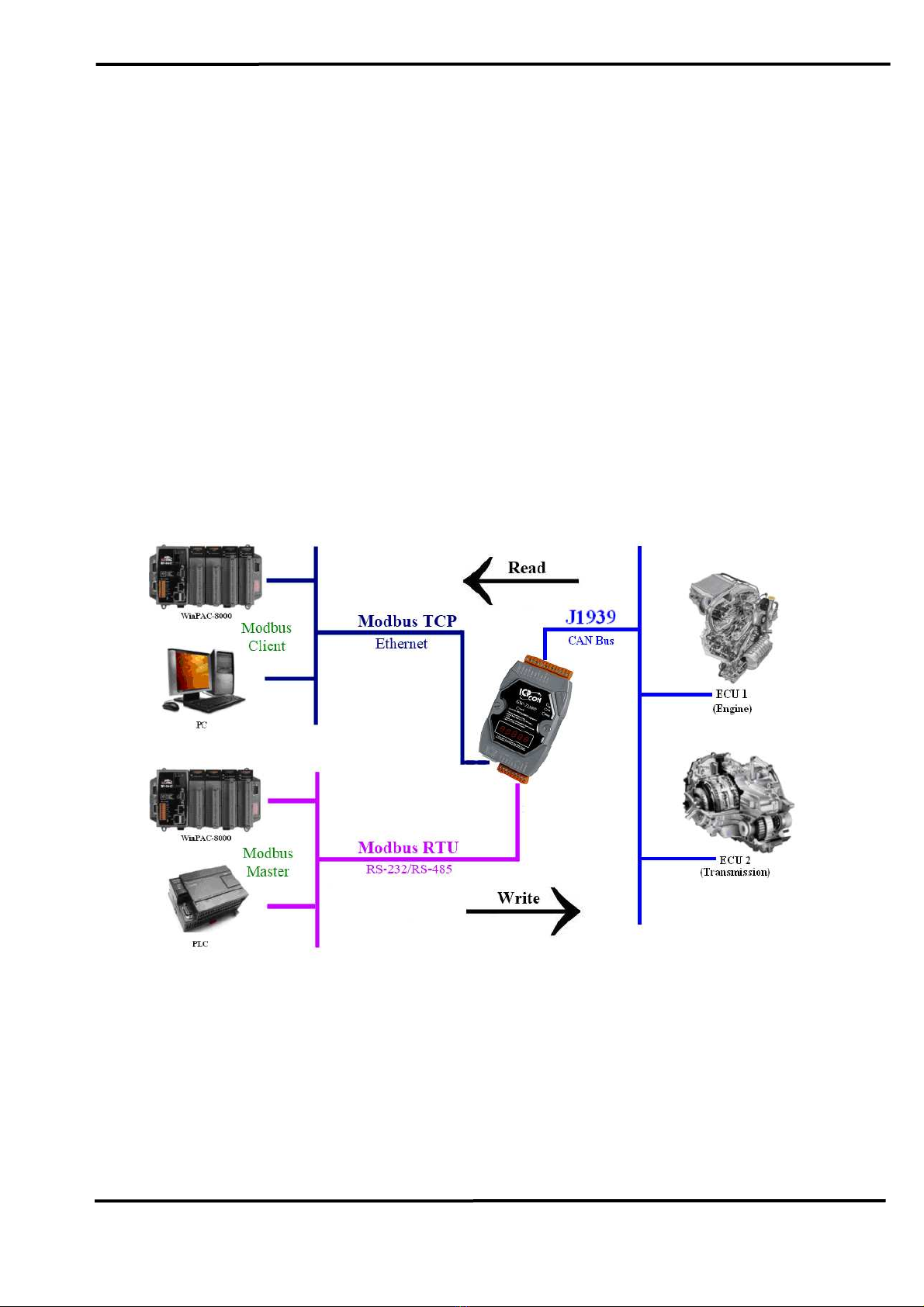
The GW-7238D is a gateway that provides conversion between
J1939 and Modbus TCP/RTU protocol. For J1939 network, the GW-
7238D supports PDU1, PDU2, broadcast and destination specific type of
J1939 messages. For Modbus TCP/RTU network, the GW-7238D is a
Modbus TCP server / RTU slave to reply the request from Modbus TCP
client / RTU master. Utility software is provided for users to configure
J1939 and Modbus TCP/RTU setting in the GW-7238D. The application
fields can be diesel power-train applications, In-Vehicle networks for
trucks and buses, etc.
The following is the application architecture for the GW-7238D:
Figure 1-1:Application of the GW-7238D
1.1 Mode of operation
The GW-7238D provides centralized data storage, for data that is
shared between the Modbus and J1939 networks. Data is placed into the
GW-7238D by one network interface, and allowing the data to be read or
written through the other network interface.

GW-7238D J1939 to MBTCP Server / MBRTU Slave Gateway User’s Manual (Ver.1.0, Nov. 2011) --- 6
1.2 Features
•RoHS Design.
•Provide PWR / ERR / J1939 / MODBUS indication LEDs.
•The built-in jumper to select 120 ohm terminal resister of CAN bus
•Watchdog inside.
•Transmission and reception of all types of J1939 messages, including
PDU1, PDU2, broadcast and destination specific.
•J1939 Transport Protocol for transmission and reception of large
messages (9 - 1785 bytes).
•Support BAM of Connection Management Message.
•Network addresses management.
•Support RS-232, RS-485 and Ethernet interfaces.
•Support Modbus TCP server / RTU slave protocol
.
•Communication support both Modbus TCP / RTU to J1939 at the same
time.
•Configurable UART baud rates of 9600, 19200, 38400, 57600,
115200 bps.
•Allow Max 5 Modbus TCP clients to access GW-7238D simultaneously.
•Support Function Code 03 / 04 / 06 / 16 of Modbus functions for
reading and writing J1939 Messages.
1.3 Specifications
[UART specs:]
•COM1 :RS-232
•COM1 Connector:5-pin screwed terminal block (TXD1, RXD1, RTS1,
CTS1 and GND1)
•COM2 :RS-485(Self-turner inside)
•COM2 Connector :2-pin screwed terminal block (D2+, D2-)
•Baud Rate (bps): 9600, 19200, 38400, 57600 and 115200
[Ethernet specs:]
•Controller :10/100Base-TX Ethernet Controller (Auto-negotiating,
Auto-MDIX)
[CAN specs:]
•Controller :NXP SJA1000T with 16 MHz clock
•Transceiver :NXP 82C250
•Channel number :1
•Connector :5-pin screwed terminal block (CAN_L, CAN_H, N/A for

GW-7238D J1939 to MBTCP Server / MBRTU Slave Gateway User’s Manual (Ver.1.0, Nov. 2011) --- 7
others)
•Baud Rate (bps) :250 k
•Isolation :1000 VDC for DC-to-DC, 2500 Vrms for photo-couple
•Terminator Resistor :Jumper for 120 Ωterminator resistor
•Specification :ISO-11898-2, CAN 2.0A and CAN 2.0B
[Module specs:]
•Dimensions :122mm x 72mm x 33mm (L x W x H)
•Operating temperature :-25 to 75ºC (-13 to 167ºF)
•Storage temperature :-30 to 80ºC (-22 to 176ºF)
•Humidity :10 to 90%, non-condensing
•LEDs :PWR LED for power
ERR LED for error status
J1939 LED for J1939 communication
MODBUS LED for Modbus communication
[Power specs:]
•Power supply :Unregulated +10 ~ +30 VDC
•Protection :Power reverse polarity protection, Over-voltage brown-out
protection
•Power Consumption :2W
[Software Utility Tool:]
•Provide Modbus network configuration interface.
•Provide J1939 network configuration interface – Network Address /
Device Name, etc.
•Provide J1939 Input / Output configuration interface.
•Provide Modbus monitoring interface.
[Application:]
•Diesel power-train applications
•In-Vehicle networks for trucks and buses
•Truck-Trailer connections
•On Board Diagnostics
•Vehicle Automation

GW-7238D J1939 to MBTCP Server / MBRTU Slave Gateway User’s Manual (Ver.1.0, Nov. 2011) --- 8
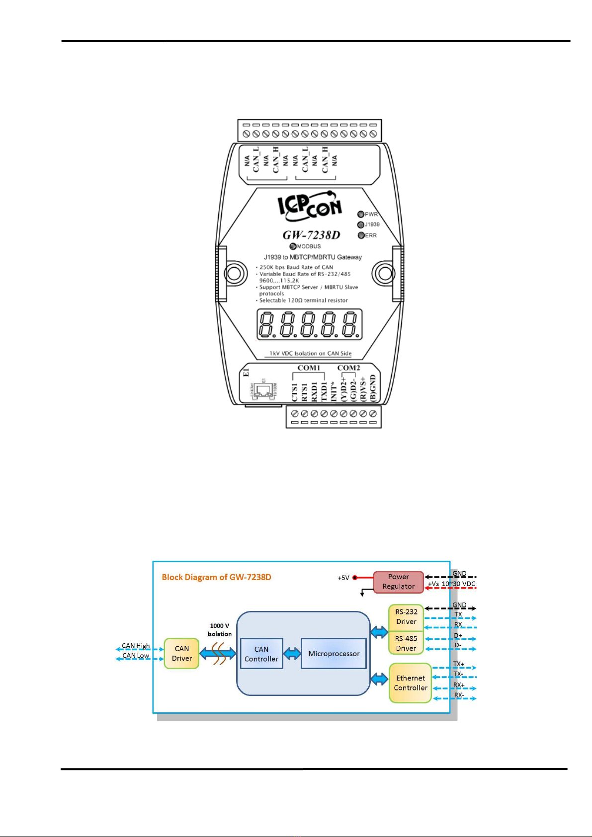
2. Hardware
Figure 2-1:Hardware externals of the GW-7238D
2.1 Block Diagram
Figure 2-2 is a block diagram illustrating the functions on the GW-
7238D module. It provides the 1000Vrms Isolation in the CAN interface
site.
Figure 2-2:Block diagram of the GW-7238D

GW-7238D J1939 to MBTCP Server / MBRTU Slave Gateway User’s Manual (Ver.1.0, Nov. 2011) --- 9
2.2 Pin Assignment
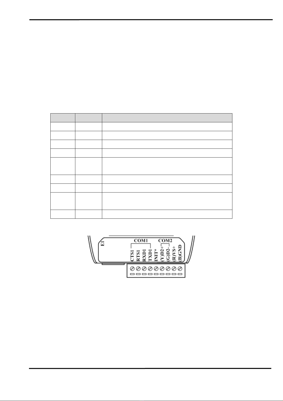
2.2.1 RS-232 & RS-485 & Power supply Interface
The GW-7238D provides one RS-232 interface and one RS-485
interface with hardware flow control. The GND-signal of COM1 is shared
with pin-9, GND. The pin assignment is shown in table 2-1.
Table 2-1:COM Connector Pin Assignment
Pin No.
Name
Description
1 CTS1 CTS pin of COM1 (RS-232)
2 RTS1 RTS pin of COM1 (RS-232)
3 RXD1 RXD pin of COM1 (RS-232)
4 TXD1 TXD pin of COM1 (RS-232)
5 INIT* Initial pin for enable/disable
AUTOEXEC.BAT
6 D2+ Data+ pin of COM2 (RS-485)
7 D2- Data- pin of COM2 (RS-485)
8 VS+ V+ of power supply
(+10V to +30V DC unregulated)
9 GND GND of power supply
Figure 2-3:COM Connector on the GW-7238D
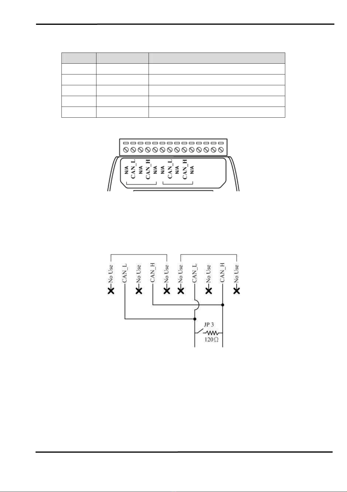
2.2.2 CAN bus Interface
In order to provide an easy CAN bus wiring, the GW-7238D supplies
one CAN port with two CAN bus connector interfaces. Each connecter
built on the GW-7238D looks like as figure 2-4 and table 2-2.

GW-7238D J1939 to MBTCP Server / MBRTU Slave Gateway User’s Manual (Ver.1.0, Nov. 2011) --- 10
Table 2-2:CAN bus Connector Pin Assignment
Pin No.
Name Description
1 N/A Not Connected
2 CAN_L CAN_L bus line (dominant low)
3 N/A Not Connected
4 CAN_H CAN_H bus line (dominant high)
5 N/A Not Connected
Figure 2-4:CAN bus Connector on the GW-7238D
Note that the bypass CAN bus connector is not another CAN channel.
It is designed for connecting to another CAN device conveniently. The
structure of the inside electronic circuit is displayed as figure 2-5.
Figure 2-5:Electronic circuit of CAN bus connector
2.2.3
Ethernet Connect
The Ethernet (10/100 Base-TX) signals are routed to an RJ45 socket
for easy connection using a standard CAT 3 or CAT 5 network cable. On
power on of the GW-7238D, it will auto-negotiate the network speed and
connection.
Table des matières
Autres manuels ICPDAS Porte
Manuels Porte populaires d'autres marques

LST
LST M500RFE-AS Manuel utilisateur

Kinnex
Kinnex Media Gateway Manuel utilisateur

2N Telekomunikace
2N Telekomunikace 2N StarGate Manuel utilisateur

Mitsubishi Heavy Industries
Mitsubishi Heavy Industries Superlink SC-WBGW256 Manuel utilisateur

ZyXEL Communications
ZyXEL Communications ZYWALL2 ET 2WE Manuel utilisateur

Telsey
Telsey CPVA 500 - SIP Manuel utilisateur