
HPE Apollo 4530 Gen9 Instructions d'utilisation et de sécurité

HPE Apollo 4530 Gen9 Chassis Setup
and Installation Guide
Part Number: 819252-005
Published: September 2018
Edition: 5
Abstract
This document contains setup, installation, and configuration information for the HPE Apollo
4530 Gen9 Chassis. This document is for the person who installs, administers, and
troubleshoots servers and storage systems. Hewlett Packard Enterprise assumes you are
qualified in the servicing of computer equipment and trained in recognizing hazards in
products with hazardous energy levels.

© Copyright 2015, 2018 Hewlett Packard Enterprise Development LP
Notices
The information contained herein is subject to change without notice. The only warranties for Hewlett
Packard Enterprise products and services are set forth in the express warranty statements accompanying
such products and services. Nothing herein should be construed as constituting an additional warranty.
Hewlett Packard Enterprise shall not be liable for technical or editorial errors or omissions contained
herein.
Confidential computer software. Valid license from Hewlett Packard Enterprise required for possession,
use, or copying. Consistent with FAR 12.211 and 12.212, Commercial Computer Software, Computer
Software Documentation, and Technical Data for Commercial Items are licensed to the U.S. Government
under vendor's standard commercial license.
Links to third-party websites take you outside the Hewlett Packard Enterprise website. Hewlett Packard
Enterprise has no control over and is not responsible for information outside the Hewlett Packard
Enterprise website.

Contents
Planning the installation.........................................................................5
Verifying the pallet contents.......................................................................................................... 5
Warnings and cautions..................................................................................................................6
Space and airflow requirements................................................................................................... 7
Temperature requirements............................................................................................................7
Power requirements......................................................................................................................8
Grounding requirements............................................................................................................... 8
Identifying components and LEDs........................................................ 9
Front panel components............................................................................................................... 9
Storage display LEDs.......................................................................................................10
Server front panel components........................................................................................ 11
Server front panel LEDs and buttons............................................................................... 11
Rear panel components..............................................................................................................12
Power supply LEDs .........................................................................................................13
Management module components...................................................................................14
Management module LEDs..............................................................................................14
I/O module components................................................................................................... 15
I/O module LEDs..............................................................................................................16
PCIe slot definitions (standard I/O module)..................................................................... 16
PCIe slot definitions (I/O module with x16 riser option)................................................... 17
HPE Smart Array P440 Controller port identification....................................................... 18
HPE H240 Smart Host Bus Adapter port identification.................................................... 19
I/O module power connector identification....................................................................... 19
LFF drive bay numbering............................................................................................................ 20
LFF drive LED definitions............................................................................................................20
Installing the chassis............................................................................22
Setting up and installing the chassis...........................................................................................22
Disassembling the chassis..........................................................................................................22
Installing the chassis into the rack.............................................................................................. 26
Installing the system components into the chassis..................................................................... 29
Installing a server............................................................................................................. 29
Installing a hot-plug drive................................................................................................. 30
Installing a flex slot power supply.....................................................................................31
Installing the system fan...................................................................................................32
Installing a management module..................................................................................... 33
Installing the expansion board......................................................................................... 33
Installing an I/O module................................................................................................... 35
Installing the HPE Smart Storage Battery option............................................................. 36
Cabling and powering up the chassis.................................................38
Cabling the chassis.....................................................................................................................38
Installing the cable management arm.............................................................................. 38
Converting the cable management arm for opposite side mounting................................40
I/O module option cabling................................................................................................ 41
3

HPE Smart Array P440 Controller cabling............................................................ 42
HPE H240 Smart Host Bus Adapter cabling......................................................... 42
Powering up the system..............................................................................................................42
Hot-plug power supply calculations..................................................................................43
Power capping............................................................................................................................ 43
Power capping modes......................................................................................................43
Configuring a power cap.................................................................................................. 44
Setting the chassis power cap mode with the PPIC utility.....................................44
Setting the chassis power cap mode with HPE APM............................................ 44
Troubleshooting.................................................................................... 46
Important safety information ...................................................................................................... 46
Symbols on equipment.....................................................................................................46
Troubleshooting resources..........................................................................................................47
Specifications........................................................................................48
Environmental specifications ..................................................................................................... 48
Chassis specifications ................................................................................................................48
Power supply specifications........................................................................................................48
HPE 800W Flex Slot Platinum Hot-plug Low Halogen Power Supply..............................49
HPE 800W Flex Slot -48VDC Hot-plug Low Halogen Power Supply...............................49
HPE 800W Flex Slot Titanium Hot-plug Low Halogen Power Supply.............................. 51
HPE 800W Flex Slot Universal Hot-plug Low Halogen Power Supply.............................51
HPE 1400W Flex Slot Platinum Plus Hot-plug Power Supply..........................................52
Hot-plug power supply calculations............................................................................................ 53
Environmental considerations.............................................................54
Communications interference..................................................................................................... 54
Preventing electrostatic discharge.............................................................................................. 54
Grounding methods to prevent electrostatic discharge...............................................................54
Websites................................................................................................ 56
Support and other resources...............................................................57
Accessing Hewlett Packard Enterprise Support......................................................................... 57
Accessing updates......................................................................................................................57
Customer self repair....................................................................................................................58
Remote support.......................................................................................................................... 58
Warranty information...................................................................................................................58
Regulatory information................................................................................................................59
Documentation feedback............................................................................................................ 59
Acronyms and abbreviations...............................................................60
4


Item Description
10 Power supply blank
11 Rack rails and cable management arm2
1 The quantity depends on the configuration ordered.
2 Not shown
Warnings and cautions
WARNING: To reduce the risk of personal injury or damage to equipment, heed all warnings and
cautions throughout the installation instructions.
WARNING: To reduce the risk of personal injury or damage to the equipment, be sure that:
• The rack is bolted to the floor using the concrete anchor kit.
• The leveling feet extend to the floor.
• The full weight of the rack rests on the leveling feet.
• The racks are coupled together in multiple rack installations.
• Only one component is extended at a time. If more than one component is extended, a rack
might become unstable.
WARNING: The chassis is very heavy. To reduce the risk of personal injury or damage to the
equipment:
• Observe local occupational health and safety requirements and guidelines for manual material
handling.
• Remove all installed components from the chassis before installing or moving the chassis.
• Use caution and get help to lift and stabilize the chassis during installation or removal, especially
when the chassis is not fastened to the rack.
WARNING: To reduce the risk of personal injury or damage to the equipment, you must adequately
support the chassis during installation and removal.
WARNING: Always have at least two people to lift the chassis into the rack. If the chassis is being
loaded into the rack above chest level, an additional person must assist with aligning the chassis
with the rails while the other people support the weight of the chassis.
WARNING: Be sure to install enclosures starting from the bottom of the rack and work your way up
the rack.
WARNING: To reduce the risk of personal injury from hot surfaces, allow the drives and the internal
system components to cool before touching them.
6Planning the installation

WARNING: To reduce the risk of electric shock or damage to the equipment:
• Never reach inside the chassis while the system is powered up.
• Perform service on system components only as instructed in the user documentation.
CAUTION: Always be sure that equipment is properly grounded and that you follow proper
grounding procedures before beginning any installation procedure. Improper grounding can result in
ESD damage to electronic components. For more information, see Preventing electrostatic
discharge.
CAUTION: When performing non-hot-plug operations, you must power down the chassis and/or the
system. However, it may be necessary to leave the chassis powered up when performing other
operations, such as hot-plug installations or troubleshooting.
Space and airflow requirements
To enable servicing and ensure adequate airflow, observe the following spatial requirements when
deciding where to install a rack:
• Leave a minimum clearance of 121.9 cm (48.0 in) in front of the rack and between rows of racks.
• Leave a minimum clearance of 76.2 cm (30.0 in) in back of the rack for a single row of racks or after
the final row of racks.
Hewlett Packard Enterprise Rack products draw cool air in through the front and expel warm air through
the rear of the enclosure. Therefore, the front of the rack enclosure must be adequately ventilated to
enable ambient room air to enter the enclosure, and the rear of the enclosure must be adequately
ventilated to enable the warm air to escape from the enclosure.
IMPORTANT: Do not block the ventilation openings.
If the front of the rack is not completely filled with components, the remaining gaps between the
components can cause changes in the airflow, which can adversely affect cooling within the rack. Cover
these gaps with blanking panels.
CAUTION: Always use blanking panels to fill empty vertical spaces in the rack. This arrangement
ensures proper airflow. Using a rack without blanking panels results in improper cooling that can
lead to thermal damage.
Racks provide proper server cooling from flow-through perforations in the front and rear doors that
provide a 65% open area for ventilation.
Temperature requirements
To ensure continued safe and reliable equipment operation, install or position the rack in a well-ventilated,
climate-controlled environment.
The operating temperature inside the rack is always higher than the room temperature and is dependent
on the configuration of equipment in the rack. Check the TMRA for each piece of equipment before
installation.
Planning the installation 7

CAUTION: To reduce the risk of damage to the equipment when installing third-party options:
• Do not permit optional equipment to impede airflow around the chassis or to increase the internal
rack temperature beyond the maximum allowable limits.
• Do not exceed the manufacturer’s TMRA.
Power requirements
Installation of this equipment must comply with local and regional electrical regulations governing the
installation of IT equipment by licensed electricians. This equipment is designed to operate in installations
covered by NFPA 70, 1999 Edition (National Electric Code) and NFPA-75, 1992 (code for Protection of
Electronic Computer/Data Processing Equipment). For electrical power ratings on options, refer to the
product rating label or the user documentation supplied with that option.
WARNING: To reduce the risk of personal injury, fire, or damage to the equipment, do not overload
the AC supply branch circuit that provides power to the rack. Consult the electrical authority having
jurisdiction over wiring and installation requirements of your facility.
CAUTION: Protect the chassis from power fluctuations and temporary interruptions with a regulating
UPS. This device protects the hardware from damage caused by power surges and voltage spikes
and keeps the chassis in operation during a power failure.
Grounding requirements
This equipment must be grounded properly for proper operation and safety. In the United States, you
must install the equipment in accordance with NFPA 70, 1999 Edition (National Electric Code), Article
250, as well as any local and regional building codes.
In Canada, you must install the equipment in accordance with Canadian Standards Association, CSA
C22.1, Canadian Electrical Code.
In all other countries, you must install the equipment in accordance with any regional or national electrical
wiring codes, such as the International Electrotechnical Commission (IEC) Code 364, parts 1 through 7.
Furthermore, you must be sure that all power distribution devices used in the installation, such as branch
wiring and receptacles, are listed or certified grounding-type devices.
Because of the high ground-leakage currents associated with this equipment, Hewlett Packard Enterprise
recommends the use of a PDU that is either permanently wired to the building’s branch circuit or includes
a nondetachable cord that is wired to an industrial-style plug. NEMA locking-style plugs or those
complying with IEC 60309 are considered suitable for this purpose. Using common power outlet strips to
supply power to this equipment is not recommended.
8Planning the installation

Identifying components and LEDs
Front panel components
Item Description
1 Server bay 1
2 Server bay 1 LFF drives
3 Server bay 2
4 Server bay 2 LFF drives
5 Server bay 3
6 Server bay 3 LFF drives
7 Chassis serial label pull tab
8 Quick-release levers (2)
9 Storage LED display
Identifying components and LEDs 9
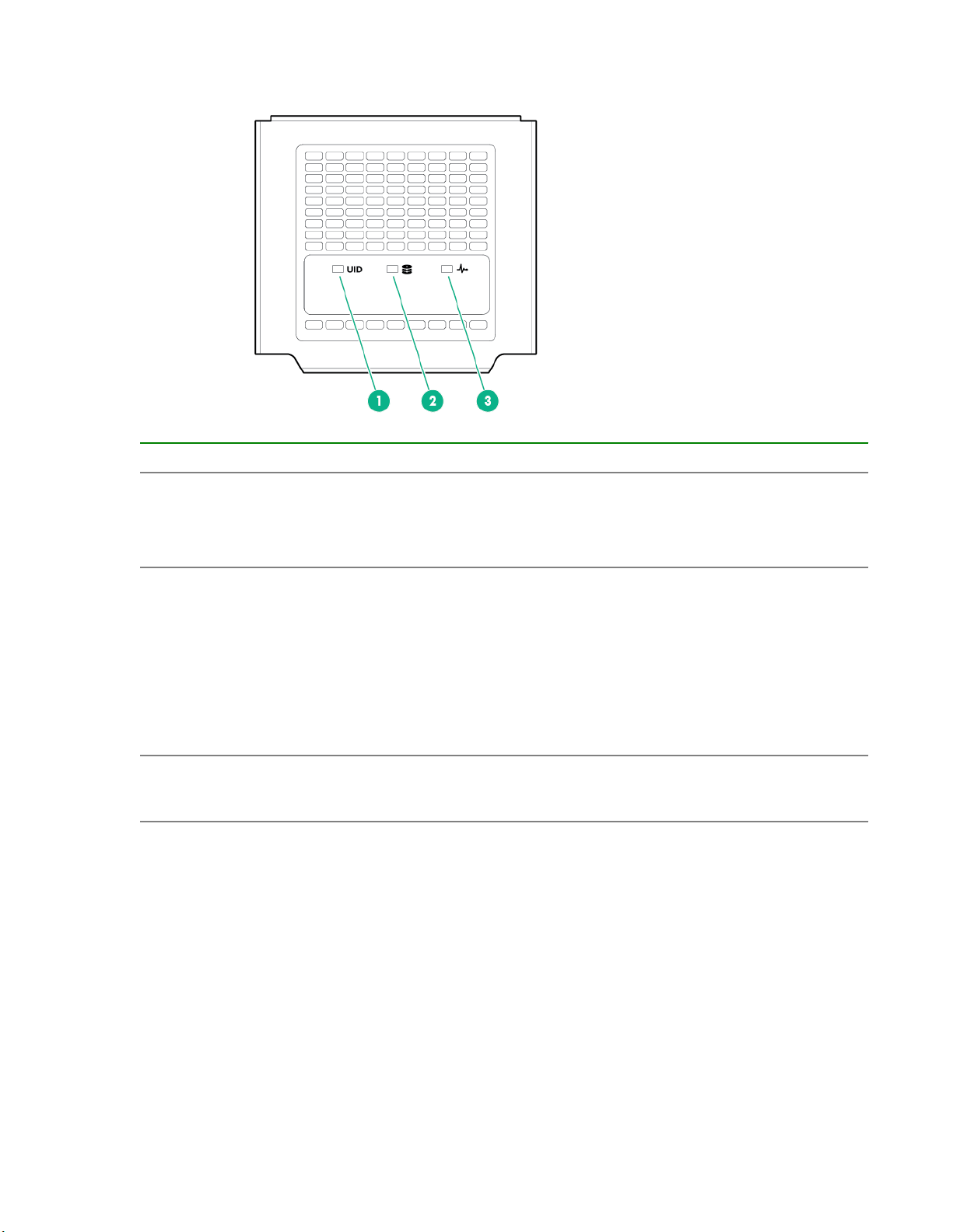
Storage display LEDs
Item LED description LED state
1 UID LED Off = Normal operating mode
Solid blue = One or more drives is in locate mode.
Flashing blue = Firmware update is in progress.
2 Drive health LED Off = No drives are configured.
Solid green = One or more drives are members of a logical drive.
Flashing green = One or more drives are rebuilding or performing a RAID
migration, stripe size migration, capacity expansion, logical drive extension,
or erasing.
Flashing amber = One or more drives are predicted to fail.
Solid amber = One or more drives have failed.
3 Backplane health
LED Green = Backplane health is normal.
Amber = Backplane error detected
10 Identifying components and LEDs
Table des matières
Autres manuels HPE Châssis

HPE
HPE Altoline 9960 C1 Instructions d'installation

HPE
HPE Apollo a6000 Manuel

HPE
HPE Apollo k6000 Manuel utilisateur

HPE
HPE Moonshot 1500 Manuel

HPE
HPE Apollo 2000 Gen10 Manuel utilisateur

HPE
HPE Apollo z70 Manuel utilisateur

HPE
HPE FlexFabric 12902E Instructions de montage

HPE
HPE Synergy 12000 Frame Instructions d'utilisation et de sécurité

HPE
HPE Synergy 12000 Frame Instructions d'utilisation et de sécurité

HPE
HPE Apollo 4510 Gen9 Instructions d'utilisation et de sécurité


