Hidrotermal HT-VS525 Manuel utilisateur

Fiberglass Filter
Side Mount Series
USER MANUAL

Fiberglass Filter Parameters
Model Filter Area
(m2)
Max Flow
Rate (m3/h)
0.5-1.2mm
Sand Weight
(kg)
Size A
(mm)
Size B
(mm)
Size C
(mm)
Size D
(mm)
HT-VS525 0.22 1.5" 50mm 12.00 85 40 47 780 525
HT-VS625 0.30 1.5" 50mm 16.00 150 45 52 880 625
HT-VS700 0.40 1.5" 50mm 20.00 210 50 57 945 700
HT-VS700B 0.40 2.0" 63mm 21.00 215 52 62 945 700
HT-VS750 0.45 2.0" 63mm 23.00 300 58 68 960 750
HT-VS800 0.50 2.0" 63mm 25.00 355 64 74 1080 800
HT-VS900 0.64 2.0" 63mm 31.00 470 65 75 1100 900
HT-VS1000 0.79 2.0" 63mm 36.00 620 70 80 1285 1000
HT-VS1100 0.96 2.0" 63mm 42.00 800 72 82 1380 1100
HT-VS1200 1.13 2.0" 63mm 45.00 900 73 83 1500 1200
Function
The filter uses special filter sand to remove dirt particles from pool water. The filter sand is loaded into the
filter tank and functions as the permanent dirt removing media. When the control valve is in the FILTER
position, the pool water which contains suspended dirt particles, is pumped through the piping system and is
automatically directed by the filter control valve to the top of the filter tank. As the pool water is pumped
through the filter, dirt particles are rapped by the sand bed, and filtered out. The cleaned Pool water is
returned from the bottom of the filter tank, through the control valve and back to the pool through the piping
system. This entire sequence is continuous and automatic and provides for total recirculation of pool water
through the filter and piping system.
After a period of time the accumulated dirt in the filter causes a resistance to the flow, making it to diminish.
This means it is time to clean your filter. With the control valve in the BACKWASH position, the water flow is
automatically reversed through the filter so that it is directed to the bottom of the tank, up through the sand,
flushing the previously trapped dirt and debris out the waste line. Once the filter is back-washed of dirt, set
control valve to the RINSE position and run the pump for about 1/2 to 1 minute, then resume to normal
filtering.
Valve
Connections
NOTE: Stop the pump before changing the valve position!
Please read and follow this MANUAL before install
and use the filter!
Figure 1

Installation
Filter's Start -Up
Required Tools: Screwdriver, Wrenches, pipe sealant and plastic adapters.
1. The filter should be placed on a reasonably level surface and provided adequate drainage. Position the filter
so that the piping connections, control valve are convenient and accessible for operations and service, The
filter should be placed as close to the pool as possible in order to reduce the line loss from pipe friction.
2. Loading the sand media. The filter sand media is loaded through the filters top opening.
a) Loosen the flange clamp and removethe filter control valve (if previously installed).
b) Cap the internal pipe with a plastic cap to prevent sand from entering it.
c) We recommend filling the tank approximately to half of it's water cappacity, in order to provide a cushion
effect when the filter sand is poured in. This helps to protect the under-drain laterals from an excessive shock.
d) Carefully pour in the correct amount and grade of filter sand. (Be sure the center pipe remains centered in
the opening.) The sand surface should be leveled and up to about the middle of the filter tank. Remove the
plastic cap from the internal pipe.
3. Assemble the filter control valve to the filter tank.
a) Insert the filter control valve (with the O-ring in place) into the tank neck, beware that the center pipe slips
into the hole at the bottom of the valve.
b) Place two plastic clamps around the valve flange and tank flange and tighten just enough so that the valve
may be rotated on the tank for final positioning.
c) Carefully screw the pressure gauge (with the O-ring in place) intothe tapped hole on the valve body. Do not
over-tighten.
d) Connect the pump to control the valve opening marked PUMP. After connections are made, tighten the
valve flange clamps with a screwdriver, tap around the clamp with a screwdriver handle to help seat the valve
flange clamp.
4. Set a return to the pool pipe connection to control the valve opening marked RETURN and complete other
necessary plumbing connections, suction as lines to the pump, waste, etc.
5. Perform the electrical connections to the pump following the pump manual.
6. Make sure all the pipe connections are tight and there are no leakages.
1. Make sure the correct amount of filter sand is in the tank and that all connections have been correctly made
and secured.
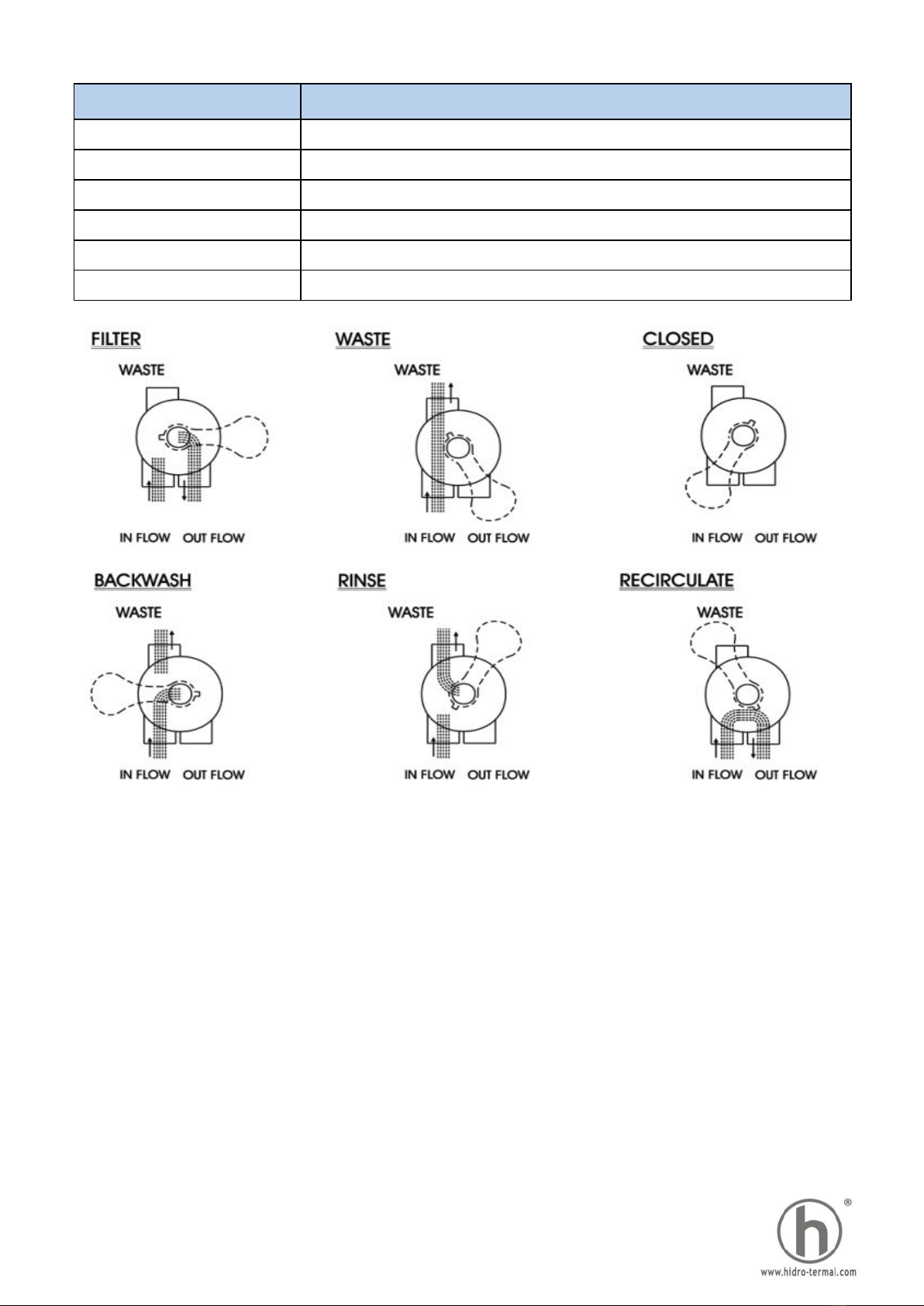
2. Push the down control valve handle and rotate to the BACKWASH position. (To prevent any damage to the
control valve seal, always push down the handle before turning.)
3. Startthe pump according to the pump manual (Make sure all thesuction and return lines are opened),
allowing the filter tank to fill in with water. Once the water is flowing out it removes any fine sand particles and
impurities from the sand media.
4. Stop the pump and set valve to the RINSE position. Start the pump and operate for 1 minute until water is
clear. Stop the pump and set the valve to the FILTER position and then restart the pump. The filter is now
operating at the normal filtering mode, removing dirt particles from the pool water.
5. Adjust the pool suction and the return valves to achieve desired flow. Check the system and the filter for
water leaks and tighten the connections, bolts, nuts, as required.
6. Acknowledge the initial pressure gauge reading when the filter is clean. (It will vary from each pool
depending on the pump and general piping system.) As the filter removes dirt and impurities from the pool
water, the accumulation in the filter will cause the pressure to rise and the flow to diminish. When the pressure
gauge reading is 1.5 BAR higher than the initial "clean" pressure you noticed, then it is time to backwash the
filter (See BACKWASH under filter and control valve functions).
Note: During the initial clean-up of the pool water it may be necessary to
backwash frequently due to the heavy initial dirt load in the pool.

Fiberglass Filter Structure
Key No. Product Description Qty
1 Air Release Valve 1
Oil Pressure Gauge with O-ring (40 psi) 1
Connector for Pressure Gauge/Stopper 1
303013003 M8 Nut*12Pc; 03012003 M8 Washer*12Pc 1
4Lid (Grey Color) 1
5 Filter Neck Gasket 1
700B Fe Ta Wh Bae 1
800 Fe Ta Wh Bae 1
900 Fe Ta Wh Bae 1
7 2.0" Side Mount Valve 1
8 Connector Plate Side Mount 1
700B T a f he e a e 1
800 T a f he e a e 1
900T a f he e a e 1
700B B a f he e a e 1
800 B a f he e a e 1
900 B a f he e a e 1
11 Laterals (233mm) 8
700B A Ve Pe 1
800 A Ve Pe 1
900 A Ve Pe 1
13 Water Drain set 1
Item No. Product Description Qty
1Handle (Big) 1
2Pin for Handle 1
3 Washer for Handle 1
4 2.0" Side Mount Valve Squareness Lid (White) 1
5 M6*32 Screw with Nut 10
6 Connector for Pressure Gauge/Stopper 1
7Drain Plug with O-ring 1
8 Oil Pressure Gauge with O-ring (40psi) 1
9 O-ring for 2.0" Union 8
10 2.0" Connector (White) 3
11 2.0" Union (A/E) 3
12 2.0" Union Nut (White) 3
13 O-ring for 2.0" Valve Lid 1
14 Washer for spring 1
15 O-ring for 2.0" Valve Rotor 2
16 Spring 1
17 2.0" Valve Rotor 1
18 Spider Gasket 1
19 2.0" Side Mount Valve Bottom Body(White) 1
20 Sight Glass With O-ring 1
21 O-ring for Union tale 1
22 2.0" Union Tale (White) 1
23 2.0" Union Nut (Black) 2
24 O-ring for Plug 1
25 2.0" Side Mount Valve Plug (White) 2
26 2.0" Elbow Tube (White) 183mm 1
27 2.0" Union Adaptor (Metric) 1
12
2. Multiport Valve Replacement Parts
1. Filter Replacement Parts
2
6
9
10
Figure 2
Figure 3

Trouble Shooting Guide
Water leaks from
drain outlet
1. The O-Ring for 1.5"Valve rotor
cover is not sealed well. (Please see
Figure 3, Item No.14-Washer for
spring)
1. Check if the washer for spring is
sealed well and adjust it.
Water leaks from the
top lid of the filter
1. The sand media diameter is too
small.
1. Check if the sand media
diameter is too small or not.
Sand media leaking
from drain outlet
2. If it was damaged please replace
it.(See Figure 3, Item No.18-Spider
Gasket).
1. The spider gasket is loose or
damaged.
(Please see Figure 3, Item No.18-
Spider Gasket)
1. Check if the spider gasket is
loose or not, adjust it.
2. Item No.14-Washer for spring is
damaged.
2. Replace item No.14 washer for
spring.(Please see Figure 3)
2. The laterals are damaged. (Please
see Figure 2, item No.11-Laterals).
2. If water outlet pipe also leaking,
that means the laterals are broken,
please replace these. (See Figure
2, item No.11-Laterals)
PROBABLE CAUSES ACTION TO BE TAKEN
Water leaks from
handle position
1. the ring under the standard lid of
handle is damaged. ( Please see
Figure 3, Item No. 3-Washer for
Handle)
1. Replace item No.3 washer
(Please see Figure 3)
SYMPTOMS

Valve Positions Function
Valve Position Function
FILTER Normal Filtration and Vacuum
BACK WASH Clean Filter by reversing the flow
RINSE Use after backwash to flush dirt from valve
WASTE By-passes filter, use to vacuum the waster for lowering water level
RECIRCULATE By-passes filter for circulating water to pool
CLOSED Shut off all flow to filter or pool
Function and Installation Scheme
I. Filtration of Medium (i.e. Water)
Pool => Pump => Valve (to filter) =>
filter => Valve (from filter) => Pool
II. Drainage of Pool with Pump
Pool => Pump => Valve => Canal
III. No Circulation
Do not operate pump.
Pool => Pump => Valve
IV. Cleaning of Filter Medium (i.e. Sand)
in upstream (reserved flow in filter)
Pool => Pump => Valve (from filter) =>
filter => Valve (to filter) => Waste
V. Recirculation of Fluid Without
Filter (by pass filter)
Pool => Pump => Valve => Pool
VI. Cleaning of Filter Medium (i.e. Sand)
after Backwash
Pool => Pump => Valve (to filter) => filter
=> Valve (from filter) => Waste

Warning
1. THIS FILTER OPERATES UNDER HIGH PRESSURE. WHEN ANY PART OF THE
CIRCULATING SYSTEM (e.g. CLAMP, PUMP, FILTER, VALVES, ETC.) IS
SERVICED, AIR CAN ENTER THE SYSTEM AND BECOME PRESSURIZED.
PRESSURIZED AIR CAN CAUSE THE LID OR VALVE TO BE BLOWN OFF WHICH
CAN RESULT IN SEVERE INJURY, DEATH, OR PROPERTY DAMAGE.
2. TURN PUMP OFF BEFORE CHANGING VALVE POSITION.
3. TO PREVENT DAMAGE TO THE PUMP AND FOR PROPER OPERATION OF
THE SYSTEM, CLEAN PUMP STRAINER AND SKIMMER BASKET REGULARLY.
4. DO NOT UNSCREW SCREWS OF FLANGE CLAMP WHILE PUMP IS RUNNING.
Ce manuel convient aux modèles suivants
9
Table des matières
Autres manuels Hidrotermal Filtre de piscine
Manuels Filtre de piscine populaires d'autres marques

Davey
Davey EcoPure DEP2140 Manuel utilisateur

JUWEL Aquarium
JUWEL Aquarium EccoSkim Manuel utilisateur

POLYGROUP LIMITED
POLYGROUP LIMITED SFS600 Filter System with F600C Pump Manuel utilisateur

Pentair Pool Products
Pentair Pool Products Filter CFW Series Manuel utilisateur

Oase
Oase Skimmer 250 Manuel utilisateur

Oase
Oase CrystalSkim 350 Manuel utilisateur


