
HBK Z6M Manuel utilisateur

Z6/M
ENGLISH DEUTSCH FRANÇAIS
Mounting Instructions
Montageanleitung
Notice de montage

Hottinger Brüel & Kjaer GmbH
Im Tiefen See 45
D-64293 Darmstadt
Tel. +49 6151 803-0
Fax +49 6151 803-9100
www.hbkworld.com
Mat.: 7-2001.6001
DVS: A01063 06 Y00 01
02.2022
EHottinger Brüel & Kjaer GmbH
Subject to modifications.
All product descriptions are for general information
only. They are not to be understood as a guarantee of
quality or durability.
Änderungen vorbehalten.
Alle Angaben beschreiben unsere Produkte in allge
meiner Form. Sie stellen keine Beschaffenheits- oder
Haltbarkeitsgarantie dar.
Sous réserve de modifications.
Les caractéristiques indiquées ne décrivent nos
produits que sous une forme générale. Elles
n'impliquent aucune garantie de qualité ou de
durabilité.

Z6/M
ENGLISH DEUTSCH FRANÇAIS
Mounting Instructions

Z6/M
TABLE OF CONTENTS
2
TABLE OF CONTENTS
1 Safety instructions 3................................................
2 Markings used 5....................................................
2.1 The markings used in this document 5.................................
2.2 Symbols on the product 5............................................
3 General 6..........................................................
4 Prior to mounting 7.................................................
5 Mounting 8........................................................
6 Operation 10........................................................
7 Mounting examples 11...............................................
8 Connection 12.......................................................
8.1 Connecting several weighing modules in parallel 13.......................
8.2 Connection using four‐wire circuitry 13..................................
8.3 Cable extensions 13..................................................
9 Dimensions 14......................................................
10 Specifications Z6/M weighing module 15...............................
11 Specifications for the Z6... load cells 16................................

3
Z6/M
SAFETY INSTRUCTIONS
1 SAFETY INSTRUCTIONS
In cases where a breakage would cause injury to persons or damage to equipment, the
user must take appropriate safety measures (such as fall protection, overload protection,
etc.). For safe and trouble‐free operation, weighing modules must not only be correctly
transported, stored, sited and installed but must also be carefully operated and main
tained.
It is essential to comply with the relevant accident prevention regulations. In particular
you should take into account the limit loads quoted in the specifications.
Use in accordance with the regulations
Z6/M... type weighing modules are conceived for weighing applications. Use for any
additional purpose shall be deemed to be not in accordance with the regulations.
In the interests of safety, the weighing modules should only be operated as described in
the Mounting Instructions. It is also essential to observe the appropriate legal and safety
regulations for the application concerned during use. The same applies to the use of
accessories.
The weighing modules are not safety elements within the meaning of its use as intended.
Proper and safe operation of this transducer requires proper transportation, correct
storage, assembly and mounting and careful operation and maintenance.
General dangers due to non‐observance of the safety instructions
The Z6/M... weighing modules correspond to the state of the art and are fail‐safe. The
tank weighing modules can give rise to residual dangers if they are inappropriately
installed and operated by untrained personnel.
Everyone involved with the installation, commissioning, maintenance or repair of a force
transducer must have read and understood the Mounting Instructions and in particular
the technical safety instructions.
Residual dangers
The scope of supply and performance of the weighing modules covers only a small area
of weighing technology. In addition, equipment planners, installers and operators should
plan, implement and respond to the safety engineering considerations of weighing
technology in such a way as to minimize residual dangers. Prevailing regulations must be
complied with at all times. There must be reference to the residual dangers connected
with weighing technology.

Z6/M
SAFETY INSTRUCTIONS
4
Environmental conditions
In the context of your application, please note that all materials which release chlorine
ions will attack all grades of stainless steel and their welding seams. In such cases the
operator must take appropriate safety measures.
Prohibition of own conversions and modifications
The weighing modules must not be modified from the design or safety engineering point
of view except with our express agreement. Any modification shall exclude all liability on
our part for any damage resulting therefrom.
Qualified personnel
These weighing modules are only to be installed by qualified personnel strictly in
accordance with the technical data and with the safety rules and regulations which
follow. It is also essential to observe the appropriate legal and safety regulations for the
application concerned. The same applies to the use of accessories.
Qualified personnel means persons entrusted with the installation, fitting, commissioning
and operation of the product who possess the appropriate qualifications for their
function.
Accident prevention
Although the specified nominal capacity in the destructive range is several times the full
scale value, the relevant accident prevention regulations from the trade associations
must be taken into consideration.
5
Z6/M
MARKINGS USED
2 MARKINGS USED
2.1 The markings used in this document
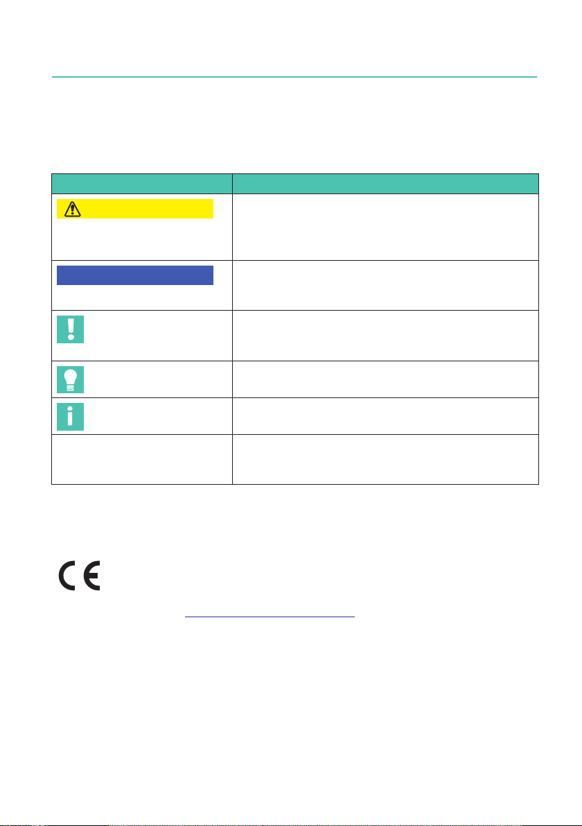
Important instructions for your safety are specifically identified. It is essential to follow
these instructions in order to prevent accidents and damage to property.
Symbol Significance
CAUTION This marking warns of a potentially dangerous
situation in which failure to comply with safety
requirements can result in slight or moderate physical
injury.
Notice This marking draws your attention to a situation in
which failure to comply with safety requirements can
lead to damage to property.
Important This marking draws your attention to important in
formation about the product or about handling the
product.
Tip This marking indicates application tips or other
information that is useful to you.
Information This marking draws your attention to information
about the product or about handling the product.
Emphasis
See …
Italics are used to emphasize and highlight text and
identify references to sections, diagrams, or external
documents and files.
2.2 Symbols on the product
CE mark
The CE mark enables the manufacturer to guarantee that the
product complies with the requirements of the relevant EC direc
tives (the declaration of conformity is available at
http://www.hbm.com/HBMdoc
).

Z6/M
GENERAL
6
3 GENERAL
HBK supplies Z6/M... weighing modules for max. capacities from 30 kg to 200 kg and
500 kg. The weighing modules are designed mainly for use in tank weighing applications.
These weighing modules are fitted with lateral stay rods. An integral over‐load stop is
also fitted.
The modules consist of a base plate, the load cell complete with load application
elements, and the cover plate. A pendulum support is used for the load application,
providing compensation for horizontal load shifts (such as may occur as a result of
thermal strain, for example). The weighing modules are pre‐assembled and a grounding
cable is supplied.

7
Z6/M
PRIOR TO MOUNTING
4 PRIOR TO MOUNTING
SCare should be taken to ensure that all surfaces for siting and mounting are clean,
smooth and level. Depending on the mounting conditions, any leveling error can be
compensated for by using suitable wedges and compensation plates (permanently
welded) or by grinding away the mounting surface, for example.
Important
On no account must the module plates be ground.
SThe base or foundation frame must be sufficiently rigid to prevent unacceptable de
formation under load (such as sagging).
SIn order to keep the mounting as free of constraining forces as possible, the fastening
holes on the foundation frame and container joint must be suitably aligned.
SEvery effort should be made to ensure uniform loading on the support points. Care
should be taken to adjust the height on the support points correctly (compensating
shims need to be available). This is especially important in the case of statically unde
fined supports.

Z6/M
MOUNTING
8
5 MOUNTING
SThe module is delivered with lifted cover plate. Prior to mounting, the cover plate has
to be lowered by unscrewing the nut.
SWhen mounting the container it is important to ensure that no sudden heavy loads are
applied to the module, for instance when lowering it onto the supports. Even transient
loads can damage the load cell if they exceed its limit values.
Notice
The factory‐fitted overload stop is designed for handling overloads during normal opera
tion. It is not designed to deal with short, sharp loads imposed during mounting, as these
commonly amount to a multiple of the permissible limit values.
SIn the case of statically undefined supports, non‐uniform loading of the modules oc
curs due to flexibility as the load is taken up or due to inaccuracy in the height adjust
ment. This non‐uniformity should be checked on the individual load cells by applying
an excitation voltage and comparing the output voltages. To prevent overloads, any
large non‐uniformity should be compensated for by inserting shims under the sup
ports that are least loaded.
SWhen tanks are heavy or mounting conditions are unfavorable, the use of mounting
aids such as auxiliary supports or lifting equipment is recommended.
SThe weighing modules must be installed so that they are not exposed to lateral forces
in the initial state. This means the built‐in pendulum support must be aligned as near
to the perpendicular as possible. This is the case when the foundation and tank joint
are horizontal and the fastening holes on the foundation and container joint are suit
ably aligned.
SThe base plate and cover plate should be firmly fastened to the foundation and tank
respectively.
SThe fitted EEK4 grounding cable is used to protect against welding currents that can
damage the electronic parts of the transducers.
Table des matières
Langues :
Autres manuels HBK Unité de contrôle

Manuels Unité de contrôle populaires d'autres marques

Festo
Festo Compact Performance CP-FB6-E Manuel de la liste des pièces

Elo TouchSystems
Elo TouchSystems DMS-SA19P-EXTME Manuel utilisateur

JS Automation
JS Automation MPC3034A Manuel utilisateur

JAUDT
JAUDT SW GII 6406 Series Guide rapide

Spektrum
Spektrum Air Module System Manuel utilisateur

BOC Edwards
BOC Edwards Q Series Manuel utilisateur


