Gude Expert Net Control 2312 Manuel utilisateur

© 2019 GUDE Systems GmbH
Manual Ver. 1.1.1
valid from Firmware Ver. 1.00
User Manual
Expert Net Control 2312

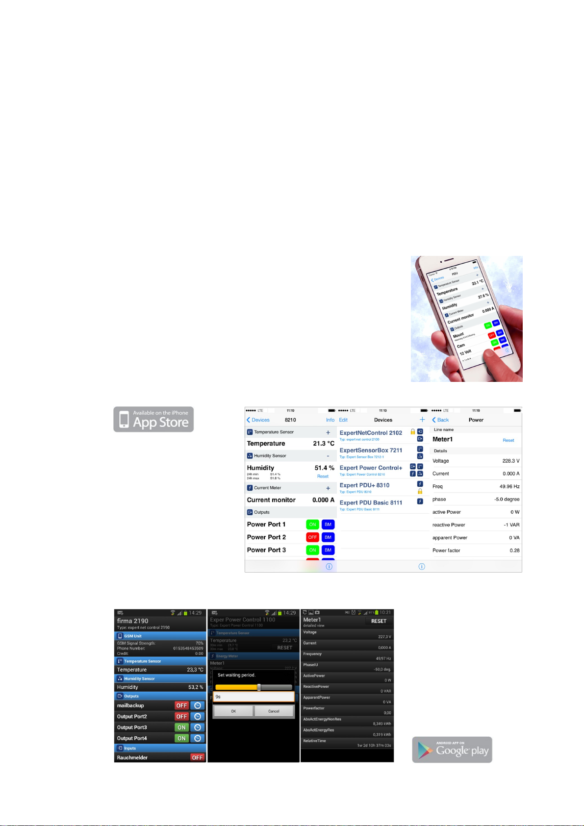
With the free Gude Control App you can retrieve all relevant information
from your GUDE products regardless of their current whereabouts.
Check with your smartphone the important operating figures of your
server and rack environment like sensor values (max/min), energy
consumption as well as state of inputs and outputs with watchdog
functions. In particular, connected consumers can be switched remotely
with Gude Control.
"Gude Control" is available for the Expert Net Control 2312 series and
can be free downloaded from the Google Play Store and iTunes Store.
Have your Gude devices always in view - and in control.

3
Expert Net Control 2312 Table of contents
Table of contents
Chapter 1 Device Description 5
5
1.1 Security Advice
5
1.2 Content of Delivery
5
1.3 Description
6
1.4 Installation
7
1.5 Stop Input
8
1.6 Block Diagram
9
1.7 Status LED
9
1.8 Bootloader Mode
10
1.9 Firmware-Update
11
1.10 Technical Specifications
11
1.11 Energy Measurement
12
1.12 Sensor
Chapter 2 Operating 13
13
2.1 Operating the device directly
13
2.2 Operating by Webinterface
14
2.3 Using the Serial Interface
Chapter 3 Configuration 15
15
3.1 Configuration by Software
17
3.2 Configuration via Webinterface
3.2.1 Configuration - Output Ports 17
3.2.2 Configuration - Watchdog 18
3.2.3 Configuration - IP Address 20
3.2.4 Configuration - IP ACL 21
3.2.5 Configuration - HTTP 22
3.2.6 Configuration - Sensors 23
3.2.7 Configuration - SNMP 24
3.2.8 Configuration - Syslog 25
3.2.9 Configuration - E-Mail 25
Chapter 4 Protocols 26
26
4.1 SNMP

5
Expert Net Control 2312 Device Description
Device Description
1
Security Advice
1.1
·The device must be installed only by qualified personnel according to the following installation and
operating instructions.
·The manufacturer does not accept responsibility in case of improper use of the device and particu-
larly any use of equipment that may cause personal injury or material damage.
·The device contains no user-maintenable parts. All maintenance has to be performed by factory
trained service personnel.
·The device may only be connected by a low voltage power supply (12V - 24V AC or DC) .
·The device is intended for indoor use only. Do NOT install them in an area where excessive moi-
sture or heat is present.
·Because of safety and approval issues it is not allowed to modify the device without our permission.
·Please note the safety advises and manuals of connected devices, too.
·The device is NOT a toy. It has to be used or stored out or range of children.
·Care about packaging material. Plastics has to be stored out of range of children. Please recycle
the packaging materials.
·In case of further questions, about installation, operation or usage of the device, which are not clear
after reading the manual, please do not hesitate to ask our support team.
Content of Delivery
1.2
The package includes:
·Expert Net Control 2312
·CD-ROM and manual
Description
1.3
The Expert Net Control 2312 is a multipurpose device that is suitable for switching and monitoring of
voltages. It has the following features:
·Suitable for top hat rail mounting
·2312: 3 switchable, potential-free relay outputs with 230V (AC 16A) switching voltage
·Measurement of current, voltage, phase angle, power factor, frequency, active power, apparent
power and reactive power per output
·Two energy counter for each output, one counter counts continuously, the other counter is resetta-
ble
·Easy to read LED display to show the total current, IP-address, sensor values and error messages
·All outputs can be switched individually on the device via HTTP, via command line tool or via serial
interface
·Switching state and delay (0 ... 9999 seconds) adjustable for each output after power failure
·Simultaneous switching of multiple outputs is prevented by automatic latency of 1 second
·1 or 3-channel watchdog to monitor the connected devices (ICMP/TCP)
·States of the relay outputs are displayed with bicolored LEDs on the front page
·Connection for an external sensor
·Programmable on / off sequence
·Possible firmware update in operation via Ethernet

6
Expert Net Control 2312 Device Description
·HTTP 1.1, E-Mail, DHCP, SNMPv1 (traps), SNMPv2c (traps), Syslog
·Access protection via IP-access control
·Access control with optional password
·Controllable via iOS and Android App
·Low own consumption
·Compatible to products of brand Solar-Log
·Developed and produced in Germany
Installation
1.4
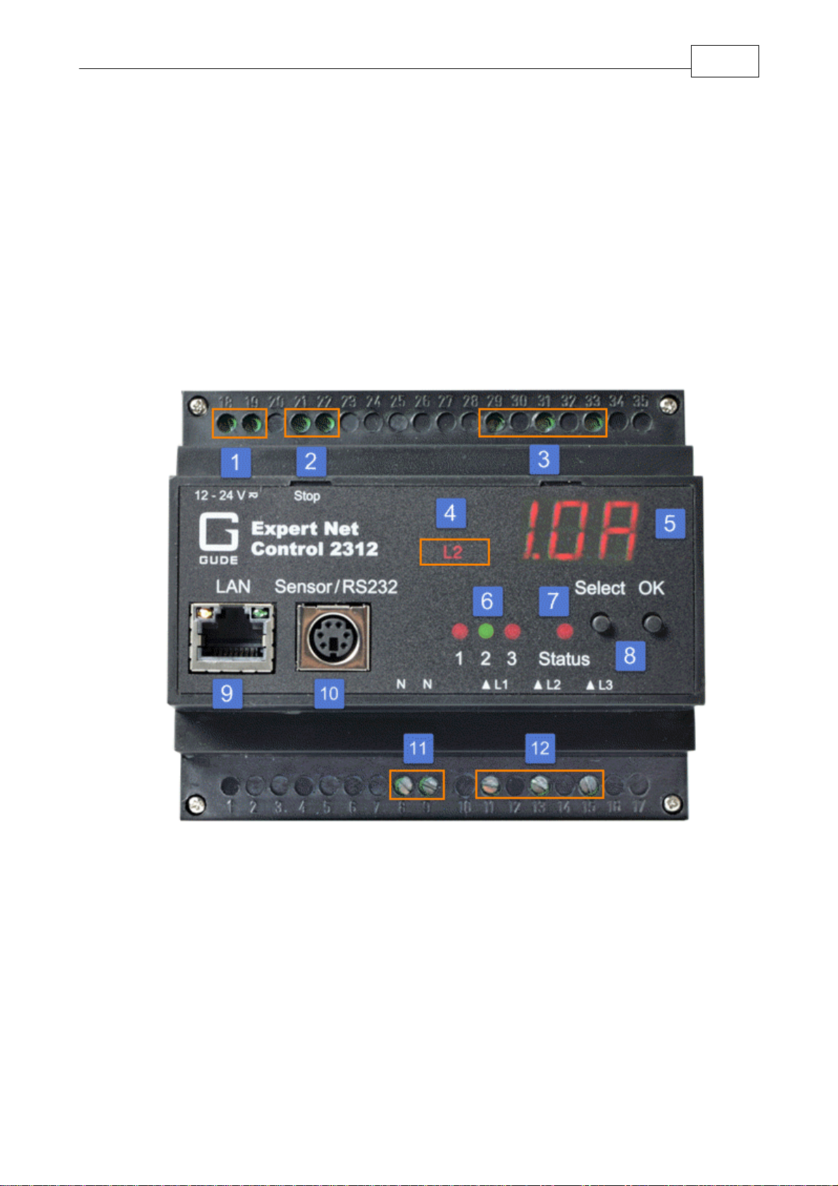
1. Power supply (12V-24V AC oder DC)
2. Stop input for shutdown of all relays
3. ENC2312: 3 relay outputs
4. L1 - L3 indicator LED display
5. LED display for load or sensor display
6. 3 indicator LEDs for relay outputs
7. Status LED
8. Button for OK, Select or bootloader mode
9. Network connector RJ45
10. Connector for sensor
11. Neutral wire connection for measurement electronics
12. ENC2312: 3 relay inputs

7
Expert Net Control 2312 Device Description
Start-up the device
·Connect the device to an AC Adaptor (12V-24V AC or DC).
·Plug the network cable into the Ethernet socket (RJ45).
·Connect the neutral wire to the neutral wire connector (11).
·Connect the relay outputs to the loads that should be used.
·Connect the relay inputs with the corresponding phase
·Attach a switch (if any) to the stop input.
·Connect the sensor (if any) to the device.
Stop Input
1.5
Stop Input
If the Stop Input is set to LOW for a second, all relays are switched off immediately. If a shutdown
was initiated, and the Stop Input goes back to HIGH for a second, the relay will re-activate as if the
device is started again. See Initialization Initialization status and Initialization delay in the chapter
"Configuration - Output Ports".

8
Expert Net Control 2312 Device Description
Block Diagram
1.6
block diagram for Expert Net Control 2312

9
Expert Net Control 2312 Device Description
Status LED
1.7
The Status LED shows different states of the device:
·red: Device is not connected to the Ethernet
·orange: Device is connected to the Ethernet, TCP/IP settings are not allocated
·green: Device is connected to the Ethernet, TCP/IP settings allocated
·periodic blinking: Device is in Bootloader mode.
Bootloader Mode
1.8
Certain actions can, for safety reasons, only be carried out if the device is in bootloader mode. The
following operations are possible only in Bootloader Mode:
·Firmware Update
·Configuration with GBL_Conf.exe
·Factory Reset
Activation of the Bootloader Mode
via push button:
·Hold both buttons for 3 seconds (only if the device has 2 buttons)
or
·Remove the power supply
·Hold down the button (or the "Select" button for devices with 2 buttons). If the push button is reces-
sed, use a pin or paper clip
·Connect the operating voltage
by Software: (only if "Enable FW to BL" was previously activated in GBL_Conf.exe)
·Start GBL_Conf.exe
·Do a network search with the "Search" menu action
·Activate in menu "Program Device" the item "Enter Bootloader"
Whether the device is in bootloader mode, is indicated by the flashing of the status LED, or it is
shown in GBL_Conf.exe, after a renewed device search, with the appendix "BOOT-LDR" after the
device name. In bootloader mode the program GBL_Conf.exe can disable the password and the IP
ACL, perform a firmware update, and restore the factory settings.
Activation of the bootloader mode and an abandonment of the bootloader does not change
the state of the power or output ports as long as the supply voltage is maintained.
Abandonment of the Bootloader Mode
via push button:
·Hold both buttons for 3 seconds (only if the device has 2 buttons)

10
Expert Net Control 2312 Device Description
or
·Remove and connect the power supply without operating a button
by Software:
·Start GBL_Conf.exe
·Do a network search with the "Search" menu action
·In menu "Program Device" activate the item "Enter Firmware"
Factory Reset
If the device is in bootloader mode, it can always be put back to its factory default. All TCP / IP set-
tings are reset in this operation.
via push button:
·Activate the Bootloader Mode of the device
·Hold down the button (or the "Select" button for devices with 2 buttons) for 6 seconds. If the push
button is recessed, use a pin or paper clip
·The status LED will blink in a fast rhythm, please wait until the LED blinks slowly (about 5 seconds)
by Software:
·Activate the Bootloader Mode of the device
·Start GBL_Conf.exe
·In menu "Program Device" activate the item "Reset to Fab Settings"
·The status LED will blink in a fast rhythm, please wait until the LED blinks slowly (about 5 seconds)
Firmware-Update
1.9
To perform a firmware update, the program GBL_Conf.exe and the latest firmware is needed.
Enable the bootloader mode (see Chapter Bootloader Mode)
Start GBL_Conf.exe
Select the device for which a firmware update is to be performed
Click "Program Device" and then select there "Firmware Update"
Specify the firmware file that should be uploaded
Upon completion of the update process, please start the new firmware of the device. You can do this
by simply leaving the bootloader mode.
A firmware update, unlike other functions, is not sent as a network broadcast. Therefore, the device
must have a valid IP address and a valid netmask before the firmware update. If necessary, please
correct the entries in GBL_Conf.exe in bootloader mode and save them with "Save Config".
If after a firmware update, the web page is not displayed correctly anymore, this may be related to the
interaction of Javascript with an outdated browser cache. Not always helps a Ctrl-F5, it is recommen-
ded that you manually delete the cache in the browser options. Alternatively, you can test start the
browser in "private mode".
Table des matières
Autres manuels Gude Système d'E/S