gopart FGP455239GP Manuel utilisateur

Push spreader
125LB / 55kg
DE
FR
NL
DK
ES
IT
PL
Schiebestreuer
Épandeur à pousser
Duw stooier
Skubbespreder
Carro esparcidor
Spargitore a spinta
Rozsiewacz pchany
FGP455239GP

2
UK
GENERAL WARNINGS
READ and UNDERSTAND this manual completely before using Push Spreader.
Operator must read and understand all safety and warning information, operating
instructions, maintenance and storage instructions before operating this equip-
ment. Failure to properly operate and maintain the push spreader could result in
serious injury to the operator or bystanders.
Operation Warnings
• Do not at any time carry passengers on the spreader.
• Do not allow children to play on, stand upon or climb in the spreader.
• Always inspect the spreader before using to assure it is in good working condi-
tion.
• Replace or repair damaged or worn parts immediately.
• Always check and tighten hardware and assembled parts before operation.
• Do not exceed equipment maximum load capacity of 125lb.
• Avoid large holes and ditches when transporting loads.
• Be careful when operating on steep grades (hill) the spreader may tip over.
• Do not push close to, ditches and public highways.
• Do not use spreader on windy days when spreading grass seed or herbicides.
• Always use caution when loading and unloading spreader.
• Never tow the spreader with a motorized vehicle.
Crush and Cut Hazards
• Always keep hands and feet clear from moving parts while operating the equip-
ment.
• Always clear and keep work area clean when operating.
• Always wear safety gear, eye protection, gloves and work boots when operating
the spreader.
WARNING
The warnings, cautions, and instructions outlined in this instruction manual can-
not cover all possible conditions or situations that may occur. It must be under-
stood by the operator that common sense and caution are factors which cannot be
built into this product and must be supplied by the operator.
Assembly Is Required
This product requires assembly before use. See “Assembly” section for instructions.
Because of the weight and/or size of the push spreader, it is recommended that
another adult be present to assist with the assembly. INSPECT ALL COMPONENTS closely
upon receipt to make sure no components are missing or damaged.

3
UK
HAZARD SIGNAL WORD DEFINITIONS
This is the safety alert symbol. It is used to
alert you to potential personal injury hazards.
Obey all safety messages that follow this
symbol to avoid possible injury or death.
DANGER indicates an imminently hazardous
situation which, if not avoided, will result in
death or serious injury.
WARNING indicates a potentially hazardous
situation which, if not avoided, could result in
death or serious injury.
CAUTION indicates a potentially hazardous
situation which, if not avoided, may result in
minor or moderate injury.
CAUTION used without the safety alert
symbol indicates a potentially hazardous
situation which, if not avoided, may result in
property damage.
ABOUT YOUR PUSH SPREADER
This push spreader is designed to spread a wide range of materials (Fertilizer,
Grass Seed and Ice melt). Materials such as Powders, Manure, Top Soil, Gravel,
and Mulch have the wrong physical characteristics and should not be used with
this spreader. Never exceed the rated load capacity of 125lbs when operating the
spreader.
Your spreader needs to be pushed at three miles per hour, which is a brisk walking
speed. Slower or faster speeds will change the spread patterns. Wet spreading ma-
terial will also change the spread pattern and flow rate. Clean your spreader thor-
oughly after each use. Wash between the shut off plate and bottom of the hopper.
Technical specifications on the push spreader are provided in the “Specifications”
section of this manual.
DANGER
WARNING
CAUTION
CAUTION

4
UK
CONTROLS AND FEATURES IDENTIFICATION
Read this owner’s manual before operating the equipment. Familiarize yourself
with the location and function of the controls and features. Save this manual for
future reference.
1. Handle – Pushes and moves the spreader easily.
2. Flow Control – Controls the flow of material being spread.
3. Hopper – Do not exceed rated load capacity 125lb.
4. Tires / Wheel – Do not exceed recommended rated 30PSI.
5. Impeller – Evenly distributes material.
6. Support Leg – Stabilizes load and spreader.
CAUTION
Read and follow all instructions for assembly and operation. Failure to properly
assemble this equipment could result in serious injury to the user or bystanders,
or cause equipment damage.
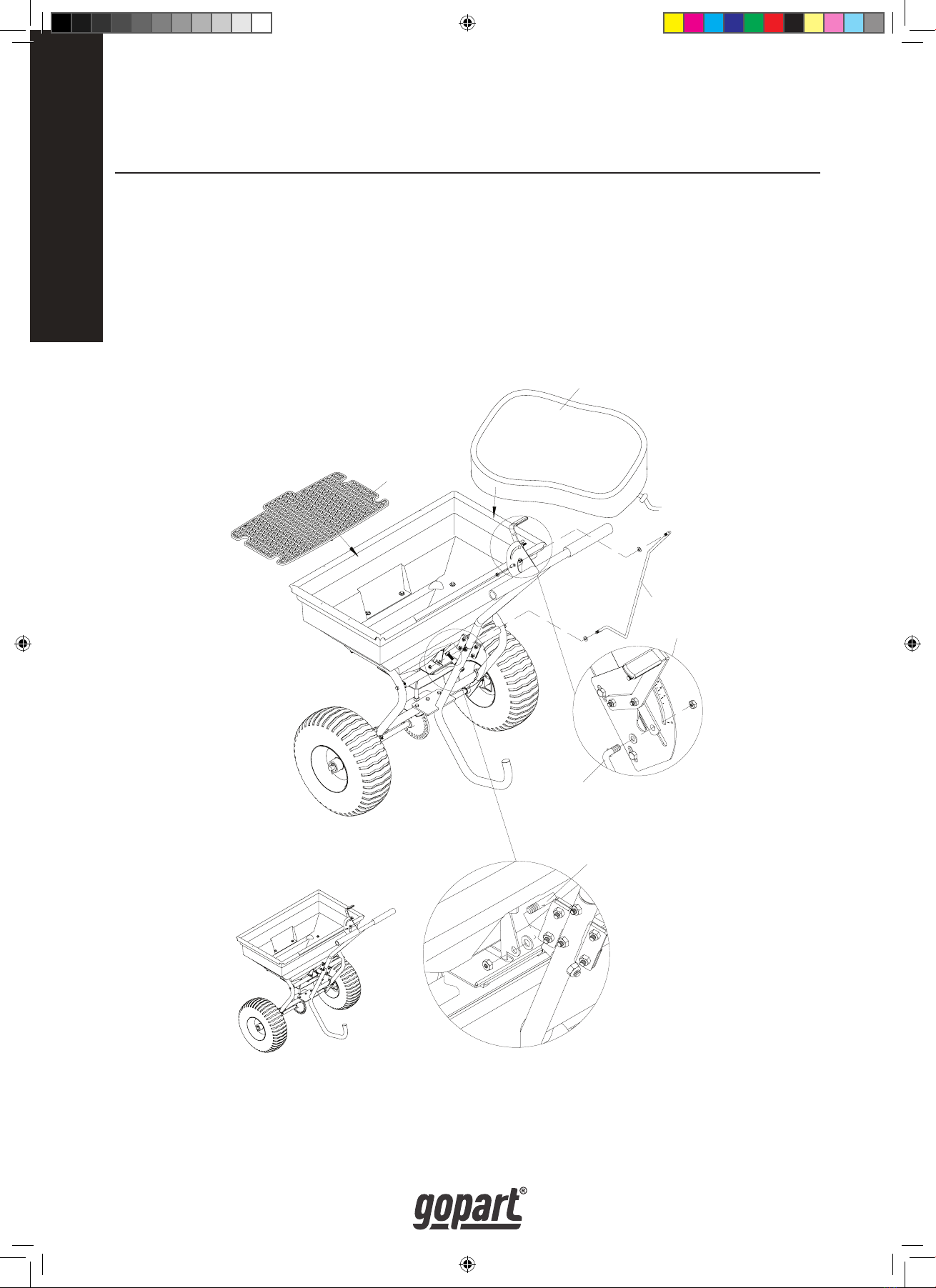
PUSH SPREADER COMPONENT PARTS AND ASSEMBLY.
Take all parts out of the shipping crate and inspect components to ensure there
are no missing pieces before starting to assemble the push spreader follow steps 1
through 5.
TOOLS REQUIRED
• Pliers (2 Each)
• 8mm Wrenches (2 Each)
• 10mm Wrenches (2 Each)
• 13mm Wrench
• 14mm Wrench
1. 2.
3.
6.
4.
5.

5
UK
COMPONENT PARTS
Hex Bolt M8X75
1 pc
Hex Bolt M6X40
6 pcs
Hex Bolt M6X35
2 pcs
Hex Bolt M6X20
4 pcs
R Pin Ø3
1 pc
Lock Nut M8
3 pcs
Lock Nut M6
12 pcs
Flat Washer Ø16
6 pcs
Flat Washer Ø8
2 pcs
Spring Washer Ø6
6 pcs
Big
Flat Washer Ø6
6 pcs
Bushing
2 pcs
Bushing
2 pcs
Drive Pin
1 pc
Spacer
1 pc
Cotter Pin Ø5X35
2pcs
㔥Ⲫ
Support Leg
1 pc
Solid Linkage
1 pc
Handle Preas-
sembled
1 pc
Hopper
1 pc
Frame Tube As-
sembly
1 pc
Wheel
2 pcs
Screen
1 pc
Rain Cover
1 pc

6
UK
1. On the left side of axle install a wheel bushing and wheel spacer into the axle.
2. Slide a wheel over the axle.
3. Put an Ø16 flat washer over the axle, insert the cotter pin through the hole
and secure by bending.
4. On the right side of the axle slide a wheel bushing and the wheel spacer into
the axle.
5. Put a wheel over the axle, line up the holes and insert the drive pin through
sleeve and lock.
6. Put an Ø16 flat washer over the axle, insert the cotter pin through the hole
and secure by bending.
NOTE: Four additional flat washers are provided for adjusting the gap between the wheels.
STEP 1: INSTALLING THE WHEELS
Cotter Pin Ø5X35
Flat Washer Ø16
Slide the Wheel Bushing and Wheel into
the Axle and align the two holes then
insert the Drive Pin.
Slide the Wheel Bush-
ing and Wheel into the
Axle
Here are 4 pcs of Flat Washers Ø16
used for adjusting the gap between
the wheels.
Flat Washer Ø16
Cotter Pin Ø5X35

7
UK
STEP 2: ASSEMBLING THE SUPPORT LEG
1. Position the support leg so the J-shaped end is pointing away from the wheel
assembly.
2. Insert the M8x75 hex bolt through the top hole on the support leg and slide
the spacer over the bolt end.
3. Take the support leg and insert the bolt through the upper cross bar on the
mounting assembly and loosely tighten with the M8 lock nut.
NOTE: Before tightening the bolt make sure the support leg flange and the lower cross bar holes line up.
4. Insert M6 x 40 hex bolt through the holes in the flange and cross bar. Use the
Ø6 big flat washer and M6 lock nut and tighten all hardware.
Frame Tube As-
sembly
Big Flat
Washer Ø6
Lock Nut M8
Hex Bolt M6X40
Support Leg
Hex Bolt M8X75
Spacer
Lock Nut M6

8
UK
STEP 3: INSTALLING THE HOPPER
1. Lower the hopper over the mounting assembly, carefully line up the holes in
the bottom of the hopper with the spindle in the mounting plate of the axle.
2. Use the M6 x 40 hex bolt and Ø6 flat washer to attach the hopper to the
mounting assembly and secure with M6 lock nut.
3. Make sure the gear and pinion gear works smoothly. If not, adjust again until
the gear and pinion gear swivel smoothly.
4. Tighten all the hardware on the shaft support plate and hopper.
5. Insert the R pin through the top of the spindle.
R Pin Ø3
Install the hopper onto the frame
tube assembly by 6 pcs of Hex
Bolt M6X40, Big Flat Washer Ø6
and Lock Nut M6
Insert the swivel
axle into the hopper
first.

9
UK
STEP 4: CONNECTING HANDLE TO THE SUPPORT LEG
1. Slide the handle tube into the top of the support leg and align the two holes.
2. Insert M6x35 hex bots through the two holes on the support leg and tighten
with the Ø6 spring washer and M6 lock nut.
3. Insert M6x20 hex bolt through the hole in the side plate and tighten with Ø6
spring washer and M6 lock nut.
Handle
Hex Bolt M6X35
Hex Bolt M6X20
Support Leg
Lock Nut M6
Spring Washer Ø6
Lock Nut M6
Spring Washer
Ø6
10
UK
STEP 5: CONNECTING THE SOLID LINKAGE
1. Connect the solid linkage through the bottom fix plate using the Ø8 flat
washer and tighten with a M8 lock nut.
2. Connect the other end of the linkage to the flow control with an Ø8 flat
washer and M8 lock nut.
3. Install the hopper screen in the bottom of the hopper.
4. Before using the spreader make sure all the hardware is tightened.
5. Use the rain cover as needed to protect material in the hopper or when
spreader is being stored.
Put the Flat washer Ø8 onto one
end of Solid Linkage. Insert it
into the hole on the Bracket and
tighten by Lock Nut M8.
Put the Flat Washer Ø8 on the
Solid Linkage and insert into the
hole. Fasten by Lock Nut M8.
Note: the bracket
needs to face oppo-
site when Assem-
bling to the handle
Screen
Rain Cover
Solid Linkage
Table des matières
Langues :
Autres manuels gopart Épandeur


Manuels Épandeur populaires d'autres marques


Fisher
Fisher POLY-CASTER 78601 Manuel utilisateur

TurfEx
TurfEx RS7200 Manuel du propriétaire

Ferris
Ferris Pathfinder Series Manuel utilisateur

Fayat Group
Fayat Group DYNAPAC S100 Guide de dépannage

Art's-Way Manufacturing
Art's-Way Manufacturing X700 Manuel d'installation et d'exploitation

EASTMAN
EASTMAN CR 500 Manuel utilisateur


