gopart FGP455210GP Manuel utilisateur

Tow-behind spreader
57kg/125LB
DE
FR
NL
DK
ES
IT
PL
Ziehbarer Streuer
Épandeur à tracter
Getrokken strooier
Trækspreder
Remolque
Esparcidor remolcado
Rozsiewacz ciągany
FGP455210GP

2
UK
Capacity: 125LB / 60L
Dimension of Hopper: 29-1/2in x16-1/2in x13-2/5in (75x42x34cm)
Length of Tow Bar: 31-7/8in (81cm)
Net Weight: 30.8lb/14kg
Overall Size: 105.5x80x80cm (41-1/2in.x31-1/2in.x31-1/2in.)
Wheel Diameter: 14in (36cm)
Wheel Width: 13cm (5in.)
IMPORTANT INSTRUCTIONS
HELPFUL HINTS:
READ THE DIRECTIONS BEFORE ASSEMBLY
WHEN ALL ELSE FAILS, READ THE DIRECTIONS AGAIN
• Read the towing vehicle owners manual and towing vehicle safety rules. Know
how to operate your tractor before using the tow-behind spreader.
• Read the chemical label instructions and cautions for handling and applying the
chemicals purchased for spreading.
• Wear eye and hand protection when handling and when applying lawn or garden
chemicals.
• Never operate tractor and spreader attachment without wearing substantial
footwear, and do not allow anyone to ride or sit on spreader attachment frame.
• Never allow children to operate the tractor or spreader attachment, and do not
allow adults to operate without proper instructions.
• Always begin with the transmission in first (low) gear and with the engine at low
speed, and gradually increase speed as conditions permit.
• When towing spreader do not drive too close to a ditch and be alert for holes
and other hazards which could cause you to loose control of the spreader and
tractor.
• Before operating vehicle on any grade (hill) refer to the safety rules in the vehi-
cle owner’s manual concerning safe operation on slopes. Stay off steep slopes!
• If your spreader does not spread evenly, be sure the FRONT on the gear box
points to the front of the spreader. The impeller must turn clockwise. Reversing
the gear box will cause the
impeller to turn counter clockwise. Clean the impeller plate after each use.
Fertilizer stuck on the impeller blades will cause uneven spreading.
• Gears are permanently lubricated at the factory. Do not open the gear box or
dirt may enter.
3
UK
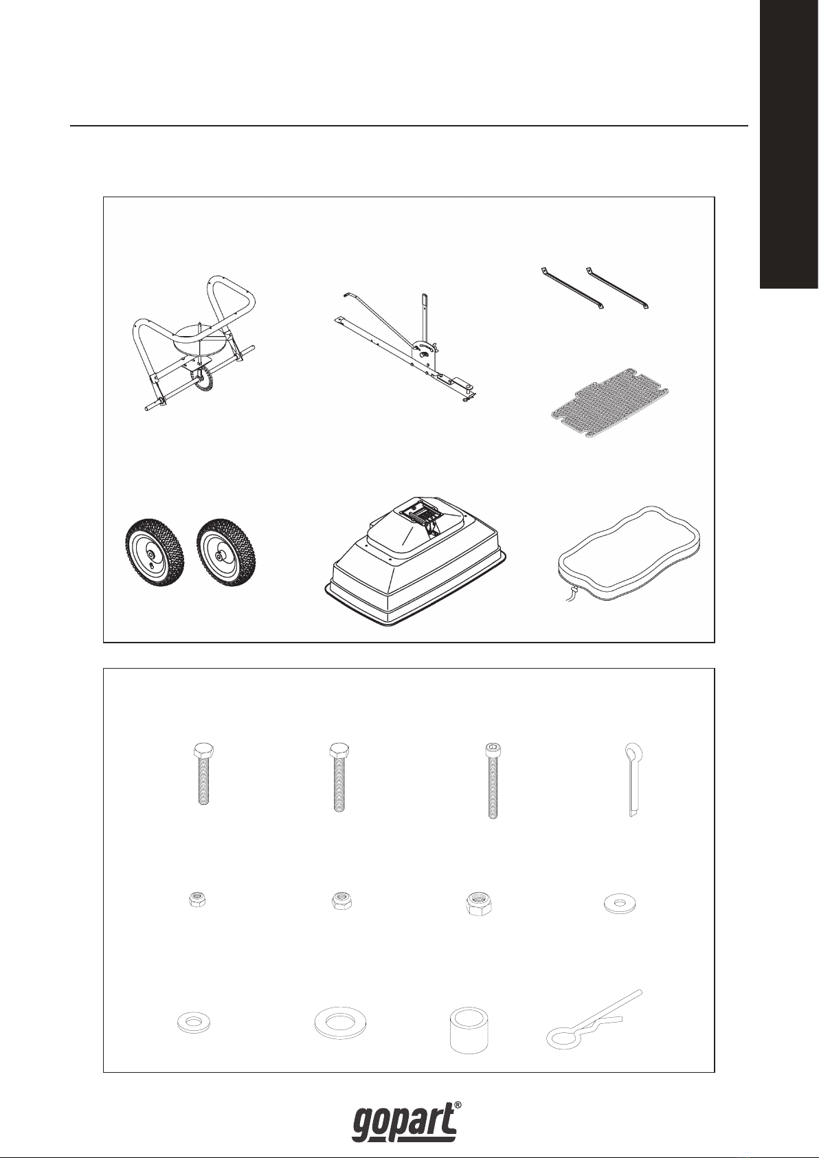
Remove and identify loose parts from carton and bag.
Hex Bolt M6X35
3 pcs
Hex Bolt M6X40
7 pcs
Inner Hex Bolt
M5X45
1 pc
Cotter Pin Ø5X35
1 pc
Nylon Lock Nut M5
1 pc
Nylon Lock Nut M6
10 pcs
Nylon Lock Nut M8
1 pc
Big Flat Washer Ø6
7 pcs
Flat Washer Ø8
1 pc
Flat Washer Ø16
5 pcs
Axle Bushing
2 pcs
R Pin
1 pc
Frame Tube Assembly
1 pc
Hitch Tube
1 pc
Brace Hitch
2 pcs
Hopper
Screen
1 pc
Hopper Assembly
1 pc
Pneumatic Wheel
2 pcs Rain Cover
1 pc

4
UK
STEP 1: ASSEMBLE WHEEL
Assemble the wheel to the Frame Tube Assembly. Fix 1pc Axle Bushing to the wheel
axle at one side of the frame tube, insert the wheel to the axle; fix the wheel with
1pc Flat Washer Ø16 and 1pc
Cotter Pin Ø5x35. (There are 4pcs extra of Flat Washer Ø16 for adjusting the space
between wheel and axle bushing.) See picture 1 & 2.
STEP 2: ASSEMBLE WHEEL
Assemble another wheel on the other side of the frame tube assembly. Insert 1pc
Axle Bushing before assemble the wheel to the axle. Fix the wheel by using 1pc
Inner Hex Bolt M5x45 and 1pc Nylon Lock Nut M5. Make sure the hole on the wheel
Aligns with the hole on the wheel axle, and then secure the wheel by inserting the
Inner Hex Bolt to the holes. Please refer Picture 3 for assembly and Picture 4 for
the position of inner hex bolt.
3
1
Axle Bushing
Frame Tube
Assembly
Flat Washer
Ø16
Wheel
Flat Washer
Ø16
Cotter Pin
Ø5X35
2
Inner Hex
Bolt M5X45
Nylon Lock
Nut M5
Axle Bushing
Wheel
4

5
UK
STEP 3: ASSEMBLE THE HITCH TUBE
Assemble the hitch tube to the middle of the frame tube assembly by using 1 pc Hex
Bolt M6x40. Secure the bolt with 1 pc Big Flat Washer Ø6 and 1 pc Nylon Lock Nut
M6. See picture 5 & 6.
STEP 4: ASSEMBLE THE BRACE HITCH
Assemble one end of Brace Hitch to the middle of the Hitch Tube, fix with 1pc Hex
Bolt M6x35 and 1 pc Nylon Lock Nut M6. See picture 7 & 8.
7
56
Hitch Tube
Hex Bolt
M6x40
Big Flat Washer
Ø6
Nylon Lock
Nut M6
8
Hex Bolt
M6X35
Brace Hitch
Brace
Hitch
Nylon Lock
Nut M6

6
UK
STEP 5: ASSEMBLE THE BRACE HITCH
Assemble another end of the Brace Hitch to the inside of Frame Tube Assembly
(Hopper Frame) by using 1pc Hex Bolt M6x35 and 1 pc Nylon Lock Nut M6
STEP 6: ASSEMBLE HOPPER
Assemble the hopper to the frame tube assembly, make sure the six holes on hop-
per align with the holes on hopper frame, then fix the hopper to frame by using 6
sets of Hex Bolt M6x40, Big Flat Washer Ø6 and Nylon Lock Nut M6. See picture 11.
If hopper is turned over please see picture 12.
9
Hopper Frame
Hex Bolt
M6X35
Nylon Lock
Nut M6
10
11 12
Big Flat
Washer Ø6
Hex Bolt
M6X40
Hopper
Nylon Lock
Nut M6
Nylon Lock
Nut M6
Hopper
Big Flat
Washer Ø6
Hex Bolt
M6X40
7
UK
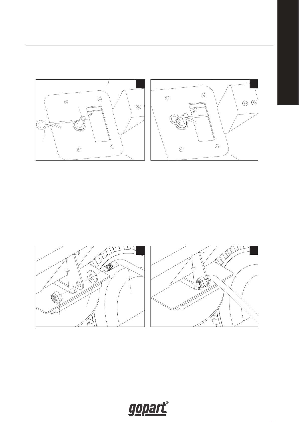
STEP 7: ASSEMBLE THE R PIN IN THE HOPPER
Assemble the R Pin to the hole of Swivel Axle in the hopper. See picture 13 & 14.
STEP 8: ASSEMBLE THE ADJUSTMENT ROD
Assemble the Adjustment Rod to the bottom of the Hopper. Insert 1pc of Flat Wash-
er Ø8 to the end of the Adjustment Rod, then insert the adjustment rod to the hole
at bottom of hopper, secure the adjustment rod with 1pc Nylon Lock Nut M8. See
picture 15 & 16.
13
Swivel
Axle
R pin
14
15
Adjustment
Rod
Flat Washer
Ø8
16
Nylon Lock
Nut M8

8
UK
NOW, YOUR SPREADER IS FULLY ASSEMBLED.
OFF ON
Move the position
of this wing nut to
alter the flow of
material

9
UK
DRAWING

10
UK
Ref# Description Qty Ref# Description Qty
1 Hopper Assembly 1 28 Swivel Axle Base 1
2 Big Flat Washer Ø6 16 29 Gear (Driver) 1
3 Hex Bolt M6x40 9 30 Wheel Axle 1
4 Rivet Ø5x10 2 31 Pin Ø4x30 1
5 Swivel Axle Bushing 2 32 Nylon Lock Nut M5 2
6 Fixed Adjustable Plate 1 33 Inner Hex Bolt M5x45 1
7 Active Adjustable Plate 1 34 Pin Ø3x16 1
8 Hex Bolt M6x20 3 35 Screw M4x20 1
9 Base for Torsion Spring 1 36 R Pin Ø3 2
10 Nylon Lock Nut M6 21 37 Impeller 1
11 Torsion Spring 1 38 Brace Hitch 2
12 Flat Washer Ø8 2 39 Hitch Tube 1
13 Fix Plate for Connecting Rod 1 40 Hitch Bracket 1
14 Nylon Lock Nut ,M8 2 41 Pin Ø12x65 1
15 Hex Bolt M6x35 7 42 Hex Bolt M6x25 2
16 Teeth Lock Washer Ø8 1 43 Carriage Bolt M6x25 1
17 Crossover Tube 1 44 Spacer 1
18 Swivel Axle Fix Plate 1 45 Wing Nut 1
19 Frame Tube Assembly 1 46 Nylon washer 1
20 Cotter Pin Ø5x35 1 47 Handle Grip 1
21 Flat Washer Ø16 7 48 Adjustable Handle 1
22 Pneumatic Wheel 2 49 Connect Rod 1
23 Wheel Axle Bushing 2 50 Gauge Plate 1
24 Inner Axle Bushing 2 51 Adjustment Rod 1
25 Outer Axle Bushing 2 52 Hopper Screen 1
26 Swivel Axle 1 53 Hex Bolt M5 x 40 1
27 Pinion Gear 1 54 Rain Cover 1
PARTS LIST
Table des matières
Langues :
Autres manuels gopart Épandeur


Manuels Épandeur populaires d'autres marques


Fisher
Fisher POLY-CASTER 78601 Manuel utilisateur

TurfEx
TurfEx RS7200 Manuel du propriétaire

Ferris
Ferris Pathfinder Series Manuel utilisateur

Fayat Group
Fayat Group DYNAPAC S100 Guide de dépannage

Art's-Way Manufacturing
Art's-Way Manufacturing X700 Manuel d'installation et d'exploitation

EASTMAN
EASTMAN CR 500 Manuel utilisateur


