Technology for safety
2 D5000 - D5200 Series - Intrinsically Safe Isolators and Safety Relays
D5000 - D5200 Intrinsically Safe Isolators and Safety Relays
Mechanical features .........................................................................................................................................................................3
Mounting and removing modules from DIN-Rail ..............................................................................................................................4
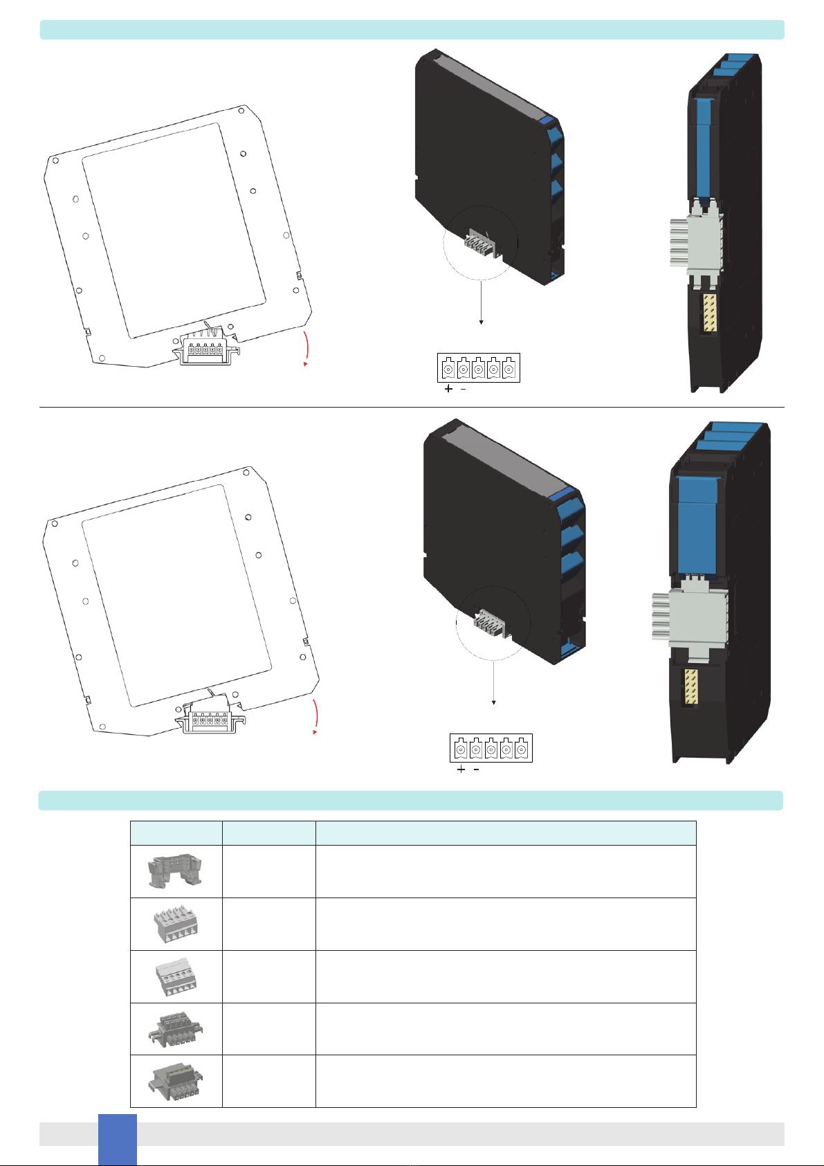
Power Bus connector.......................................................................................................................................................................6
Mounting modules on Power Bus connector....................................................................................................................................8
Ordering information ........................................................................................................................................................................8
Removing and mounting Main Case Top Cover ..............................................................................................................................9
Transparent Cover .........................................................................................................................................................................10
Terminal Blocks Connection Data..................................................................................................................................................11
Installation and removing modules from Termination Board..........................................................................................................12
Mounting Termination Board..........................................................................................................................................................14
Mounting and removing Termination Board onto DIN-Rail ............................................................................................................14
Termination Boards Characteristic.................................................................................................................................................15
Approvals and Certifications ..........................................................................................................................................................16
Storage...........................................................................................................................................................................................16
Disposal .........................................................................................................................................................................................16
Maintenance and Repair................................................................................................................................................................16
Installation of electronic equipments in cabinet..............................................................................................................................17
Heat dissipation in cabinets ...........................................................................................................................................................18
Calculation of radiant surfaces in closed cabinets .........................................................................................................................19
Placement of Isolators in cabinet ...................................................................................................................................................20
Index