www.gemu-group.com10 / 16GEMÜ 3140
8 Manufacturer's information
8 Manufacturer's information
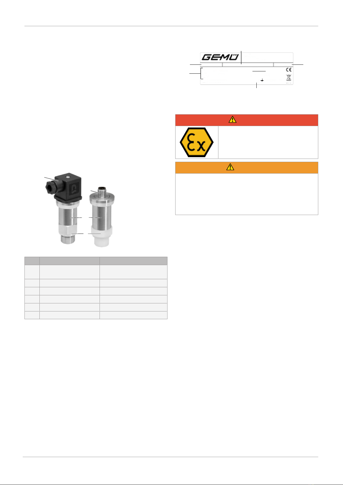
8.1 Delivery
● Check that all parts are present and check for any dam-
age immediately upon receipt.
The product's performance is tested at the factory. The
scope of delivery is apparent from the dispatch documents
and the design from the order number.
8.2 Transport
1. Only transport the product by suitable means. Do not
drop. Handle carefully.
2. After the installation dispose of transport packing mater-
ial according to relevant local or national disposal regula-
tions / environmental protection laws.
8.3 Storage
1. Store the product free from dust and moisture in its ori-
ginal packaging.
2. Avoid UV rays and direct sunlight.
3. Do not exceed the maximum storage temperature (see
chapter "Technical data").
4. Do not store solvents, chemicals, acids, fuels or similar
fluids in the same room as GEMÜ products and their
spare parts.
9 Installation in piping
9.1 Installation and safety information
DANGER
Risk of lightning strike!
▶If there is an elevated risk of the
device being damaged by lightning or
overvoltage, an effective lightning pro-
tection system must additionally be
put in place.
DANGER
Use of the product as a stepladder
▶The housings are not designed to be used as a steplad-
der for climbing in the plant. They can be damaged if
used in this way and their function impaired. If the hous-
ing is damaged, water, dirt and combustible material can
accumulate in the housing interior. This can cause a
short-circuit. Furthermore, the deposits can cause the
device to overheat and may result in an explosion.
NOTICE
▶Handle the unprotected diaphragm with extreme care, as
it is very easily damaged.
NOTICE
▶For use in steam pipes, provide a cooling zone.
NOTICE
▶During installation, avoid high mechanical stresses on
the pressure connection. This can result in the charac-
teristic shifting or in damage, particularly for very narrow
pressure ranges and for devices with a plastic pressure
connection.
NOTICE
▶With hydraulic systems, orientate the device such that
the pressure connection is facing upwards. (Vent hole)
NOTICE
▶If the device is to be installed with the pressure connec-
tion at the top, make sure that no liquid flows away along
the housing as this could result in moisture and dirt
blocking the gauge reference in the housing and, in turn,
to the equipment malfunctioning. Where necessary, re-
move dust and dirt from the edge of the electrical con-
nection's union.
NOTICE
▶Make sure that you do not remove the packaging and
protection caps from the device until you are just about
to install it, so that you do not damage the diaphragm or
the threads.
▶Keep the protection caps. Dispose of packaging properly.