Rev. 1.0
505 Keystone Rd, Southampton, PA 18966, USA . (877) 497 6937.sales@fortresspower.com .
www.fortresspower.com
2
2 – eVault MAX GENERAL DISASSEMBLY
Please refer to the following steps when disassembling the eVault Max:
1) Remove the eight (8) screws that attach the front metal cover (Appendix A-1)
2) Slowly slide off the front cover as far as the LCD wires will allow—be careful not to pull too far and
strain the LCD wires
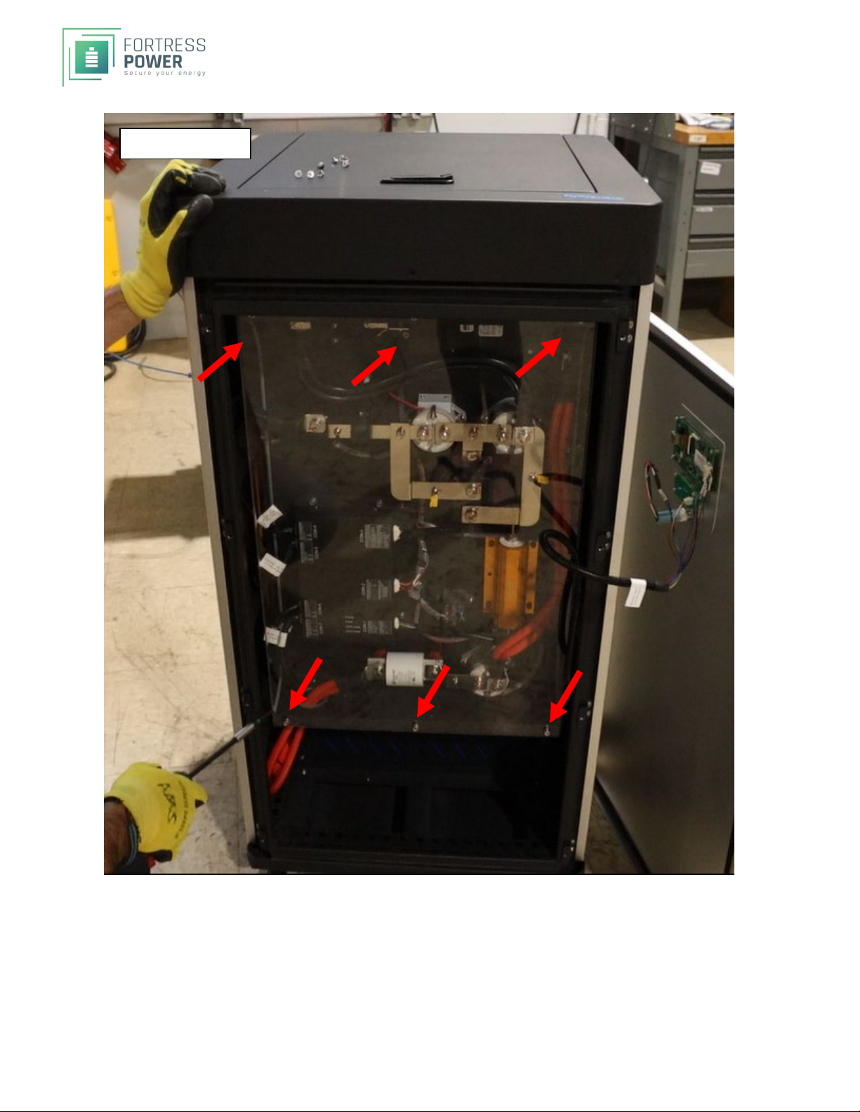
3) Remove the six (6) screws that hold the plexiglass cover (Appendix A-2)
a. You can now access the BMS panel
Steps 3 and onward are for further disassembly
4) Remove the eight (8) screws that attach the back metal cover (Appendix A-3 red)
5) Remove the eight (8) screws that attach the side metal covers (Appendix A-3 green)
6) Slide off the covers, exposing the Battery Modules
7) You should now have access to the battery internals (Appendix A-4)
8) Turn off the BMS by removing the Power cable. This connector may have some RTV Silicon on it
preventing it to be easily removed. If this is the case, carefully use a razor knife in the connector
(Appendix A-4)
3 – eVault MAX BATTERY MODULE DISASSEMBLY
Once the battery cover has been removed, it is now possible to remove the battery packs directly.SPECIAL
CARE must be taken to install everything exactly as it was including the specific location of each battery
module. Be careful not short battery internals with metal tools. If possible, use only insulated gloves once
inside the compartment.
3A – DISCONNECTING THE POWER LEADS AND BUS BARS
The battery is charged to 50 to 56 Volts. (Appendix C-2). The four Battery Packs are approximately 13 Volts
each. (Appendix C-3). TAKE EXTREME CAUTION when working with power distribution and use electrical
tape on all flexible cables to protect from shorting during disassembly and reassembly.
1) The standard color designation is BLACK for NEGATIVE (--) and RED for POSITIVE (+)
a. Failure to keep these consistent can lead to personal injury and/or battery damage
2) Make sure the battery is off. The power on the have accidently turned on when cover was removed.
3) Make sure the battery breaker is OFF
4) Label the Battery Modules 1, 2, 3, 4. Top Battery is 1, bottom is 4
5) Before proceeding have electrical tape readily for the next step
6) On the side of the battery with Bus Bars connecting the battery modules, carefully disconnect one
NEGATIVE (BLACK) Cable Lug and wrap the lug with black tape. (Appendix B-2) Then, carefully
disconnect the other NEGATIVE (BLACK) Cable Lug and wrap the lug with black tape.
7) On the side of the battery with Bus Bars connecting the battery modules, carefully disconnect one
POSITIVE (RED) Cable Lug and wrap the lug with black tape. Then, carefully disconnect the other
POSITIVE (RED) Cable Lug and wrap the lug with black tape (Appendix B-3)