First Watt F5 Turbo V3 Manuel utilisateur

F5 Turbo Assembly Instruction Version 2 Page 1
F5 Turbo V3 Assembly Instruction.
1. Introduction:
This PCB is designed base on the elson Pass F5T V3 circuit. Details please refer to the article posted by
elson on First Watt website: http://www.firstwatt.com/pdf/art_f5_turbo.pdf .
2. Circuit Diagram:
Since the PCB is layout by FETAudio and here is the circuit diagram for reference.
otes:
a. The Q7 and Q8 is in TO-92 package. I have also put TO-220 package pads in the PCB if the
original transistor recommended by elson is used.
b. J7 is a pin header and it should be shorted to ground by a jumper for normal operation. The
“X” point is for those who want to modify the power amp into F5X mode.
c. Since I use Toshiba 2SK1530 and 2SJ201 power mosfets, I have changed some values of
some components and thus please refer to the update BOM (bill of material) for details.
www.FETAudio.com

F5 Turbo Assembly Instruction Version 2 Page 2
3. Assembly Instruction:
a. Solder the ¼W resistors per BOM. ote that a gap about 1mm should be allowed between
the body of resistors to the top of PCB. This is to prevent any arcing of high voltage from
resistors to the ground plan.
b. Solder the 8 pcs film capacitors, 2 pcs LEDs, and 3 VRs. ote that the VRs P1 and P2 should
have the same direction of the P3 as shown below.
c. Solder the 3W resistors.
d. Solder the Jfets K170 and J74 (Q1 and Q2). Then solder the transistors Q7 and Q8.
e. Lastly solder the E-capacitors.
f. ote that J15 and J16 (TH1) are varistor 4k7 (black color). The leads should be insulated by
the shrink wrap provided.
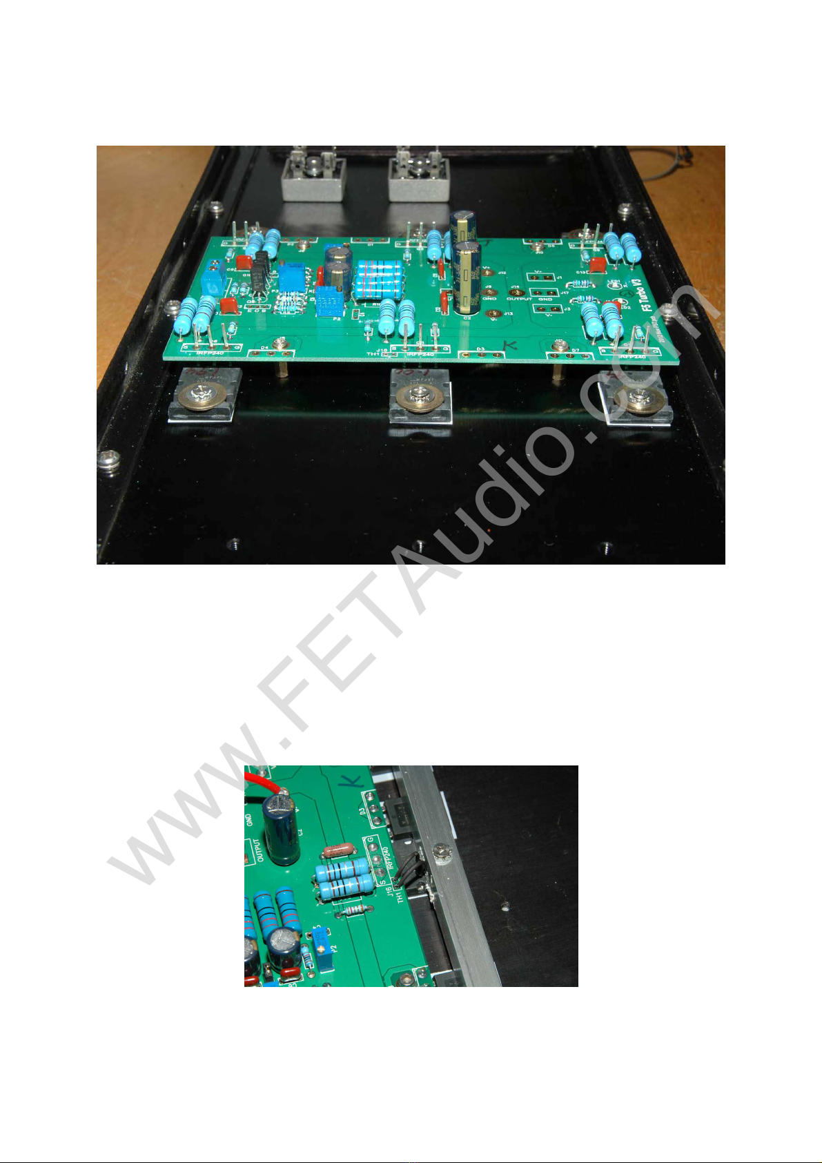
g. J6, J8, J10, & J11 are M3 holes mounting for the PCB. Use a M3 x 16mm with 10mm post
(bottom side) to mount the pcb onto the heat sink.
h. Q3, Q4 and Q9 are marked IRF9240, solder 2SJ201 at these locations.
i. Q5, Q6, and Q11 are marked IRF240, solder 2SK1530 at these locations.
www.FETAudio.com

F5 Turbo Assembly Instruction Version 2 Page 3
j. D1 – D5 and D7 are MUR3020W locations.
k. When mounting the mosfet and MUR3020W, make sure an insulation sheet is used to
isolated the body from the heat sink.
l. The drilling dimensions of the heat sink are provided at the end of this document. A heat
sink size of 200mm x 400mm is used as an example.
m. Insert the pcb mounting screws (total 4) from top and screw in a 10mm spacer post at the
bottom of the pcb.
n. When mounting the mosfet, fix them onto the heat sink as shown. Bends the leads about
90 deg upwards. Put the PCB on top and then insert all the leads (total 18) into the pad
holes of the pcb. It will take a bit time to do so. Press down the pcb and then tighten the 4
PCB screws. Tighten the screws until they are in position.
o. Loosen the mosfet mounting screws a bit so that they will release some of the force on the
leads. Tighten all the screws of the mosfets.
www.FETAudio.com

F5 Turbo Assembly Instruction Version 2 Page 4
p. ote that the MUR3020W should have their leads bended 90 deg also and then inserted
into the PCB holes from bottom of the PCB. Do not forget the insulation sheet for them. It
should be quite easy to do so as the leads of MUR3020 is just long enough to protrude out
the hole by about 1.5mm.
q. When all the PCB screws are in position and tighten, solder all the leads on top.
r. ote that the varistors should be mounted as below. The leads must not touch any ground
as it carries the +ve or –ve high voltages!
www.FETAudio.com

F5 Turbo Assembly Instruction Version 2 Page 5
s. Check the +Ve and –Ve point for any short circuit to the ground with a multi-meter. Note
that a ground plan is used in the PCB design ith a narro gap. Thus extreme care must
be taken care during soldering of any parts to prevent short circuit to the ground plane.
Due to the narro gap, the supply voltage of this PCB should not be more than +/-40V.
4. Tuning procedures:
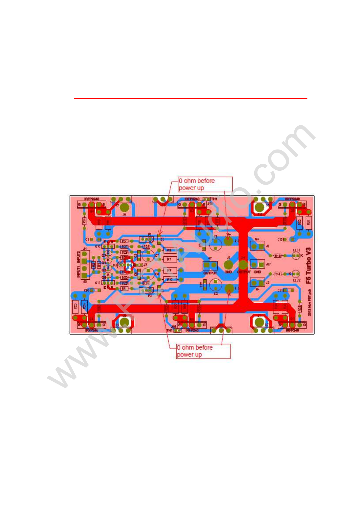
a. Before power up, adjust P1 and P2 to fully anti-clockwise if P1 and P2 is same direction as P3
Pot.
b. Check the resistance between the points show must be 0 ohm if P1 and P2 are adjusted
correctly.
c. Connect three DC meters at the locations shown.
www.FETAudio.com

F5 Turbo Assembly Instruction Version 2 Page 6
d. Power up the amplifier, the output DC offset should be close to 0V. Voltage across R20 and
R23 should also be 0V. If not, power off the amplifier immediately and trouble shoot.
e. If there is no error, then adjust P1 slowly in clockwise direction until you see the output DC
voltage start to increase. Stop at about +50mV. Then adjust P2 in clockwise direction
slowly. The DC offset at output will then drop and then stop adjust P2 when at 0V (+/-1mV).
ote the voltage drop in R20 and R23. They should be have some readings but no more
zero.
f. Target bias of 1A (for the three pairs of mosfet in total or per channel), then the voltage
across R20 and R23 should be 0.167V. If target bias is 2A, then the voltage across the R20
and R23 should be 0.333V. ote that the voltage across R20 and R23 will not be the same
but should be close within 10% if the mosfet are well matched.
g. Then repeat the step “e” until the target bias current is reached. When the voltage across
the R20 is more than 0.1V, the output dc offset should only be adjusted to up 10 to 20mV
to ensure the bias is not increased too fast. In fact when you adjust, the heat sink is cold
and thus the bias should only be 80% of the target value. The reason is that when the heat
sink is hot, the bias will increase due to thermal drift. Let the heat sink temperature stable,
re-adjust down or up until the target bias is reached. This will take about 1 hrs to stable
temperature.
h. Check through the voltage drop across all mosfet to see how good the match is. The voltage
drop or bias should be within 10% across all the mosfets. This is to ensure that all the
www.FETAudio.com

F5 Turbo Assembly Instruction Version 2 Page 7
mosfet is matched within a reasonable limit and share an almost equal load on the total
bias.
i. ote that the DC offset will drift from cold to hot and it is normal. The target is that when
hot, the dc offset should be within +/-10mV relative to ground.
j. Thus adjust the bias value according to the heat sink size used. Target temperature of the
heat sink should be below 50 degC.
k. If you do not have 3 meters, then check the output DC offset and voltage across R20. I think
two meters is a minimum.
l. For P3 pot adjustment, refer to Pass’s article for details.
m. Picture of a complete set F5 Turbo:
This set use Airlink 625VA 25Vx2 transformer, Bridge rectifier, 70000uF 50V Mallory, 1mH solen coil,
30000uF 100V Rifa long life. The ripple at the Rifa cap is below 5mV. Bias is set to 1.7A to 1.8A per
channel and heat sink temperature is 52 deg C, room temp is 20 deg C. The idle noise level is around
75uV which is very low in the AP measurement. FFT and Distortion vs Power charts are attached in this
document for reference. Distortion at 1W 8.2 ohm load is 0.004%.
Attachment follows:-
www.FETAudio.com

FET Audio 12/12/12 20:58:00 A-A 2 CHANNEL THD vs FREQ
F5T thd vs pwr.at27
ColorSweep Trace Line Style Thick Data Axis Comment
1 1 Red Solid 1 Anlr.THD+N Ratio Left Float input, lower noise
1 3 Magenta Solid 1 Anlr.THD+N Ratio Left
2 1 Green Solid 1 Anlr.THD+N Ratio Left Grounded input, higher noise
2 3 Red Solid 1 Anlr.THD+N Ratio Left
0.001
10
0.002
0.005
0.01
0.02
0.05
0.1
0.2
0.5
1
2
5
%
100m 100 200m 500m 1 2 5 10 20 50
W
T
www.FETAudio.com
Grounded Input
Floated Input

FET Audio 12/12/12 20:47:42
F5T FFT2.at27
ColorSweep Trace Line Style Thick Data Axis Comment
1 1 Red Solid 1 Fft.Ch.1 Ampl Left Set 3 : 32V supply
1 2 Magenta Solid 1 Fft.Ch.2 Ampl Left
-180
+10
-170
-160
-150
-140
-130
-120
-110
-100
-90
-80
-70
-60
-50
-40
-30
-20
-10
+0
d
B
r
A
20 20k 50 100 200 500 1k 2k 5k 10k
Hz
www.FETAudio.com

SCALE:
SHEET: OF
REVISION RECORD
APPROVED:
ECO NO:
DRAWN:
DATED:
DATED:
CHECKED:
QUALITY CONTROL:
DATED:
DATED:
RELEASED:
COMPANY:
TITLE:
A
B
D
DATE:
1
2
3
4
5
6
D
C
A
B
C
SIZE:
REV:
CODE:
LTR
DRAWING NO:
F4 POWER AMP
TH1 4k7
TH1 4k7
R2
47k
R1
1K
R3
10R
R4
10R
R27
4k7
D
G
S
Q1
2SK170
D
G
S
Q2
2SJ74
+
C7
10u
35V
+
C8
220uf
35V
G
D
S
Q3
IRF9240
G
D
S
Q5
IRF240
CW
1
2
3
P3
200R
R25
10K
CW
1
2
3
P1
5k
R29
475R
R11
2k2
R13
47R
R18
1R3W
R22
1R3W
R15
47R
G
D
S
Q6
IRF240
R14
47R
R20
1R3W
G
D
S
Q11
IRF240
R35
47R
R32
1R3W
G
D
S
Q4
IRF9240
R24
1R3W
R16
47R
G
D
S
Q9
IRF9240
R34
1R3W
R36
47R
R40
15k
J1-1
J1-2
J2-1
J2-2
J3-1
J3-2
J4-1
J4-2
K
A
LED1
J5-1
J5-2
+
C1
1000uf
35V
+
C2
1000uf
35V
C10
0.22uf
C11
0.22uf
C6
0.22uf
C5
0.22uf
Screw
J6
Screw
J8
Screw
J9
Screw
J10
Screw
J11
C3
Do not use
C4
Do not use
C9
0.22uf
C12
0.22uf
Screw
J12
Screw
J13
Screw
J14
R7
220R3W
R8
220R3W
R9
220R3W
R10
220R3W
E
C
B
Q8
2SA970BL
E
C
B
Q7
2SC2240BL
R30
475R
R5
1k
R17
1R3W
R19
1R3W
R31
1R3W
R21
1R3W
R23
1R3W
R33
1R3W
R12
2k2
R28
4k7
R6
1k
R26
10K
CW
1
2
3
P2
5k
R41
15k
K
A
LED2
J15-1
J15-2
J16-1
J16-2
J17-1
J17-2
1
2
3
D1
MUR3020W
1
2
3
D2
MUR3020W
1
2
3
D5
MUR3020W
1
2
3
D3
MUR3020W
1
2
3
D4
MUR3020W
1
2
3
D7
MUR3020W
E
C
B
Q10
KSC2690AYS
Q12
KSA1220AYS
J7-1
J7-2
C13
0.22uf
C14
0.22uf
INPUT
+32V
-32V
OUTPUT
www.FETAudio.com
Table des matières
Manuels Matériel informatique populaires d'autres marques

EMC2
EMC2 VNX Series Manuel du propriétaire

Panasonic
Panasonic DV0PM20105 Manuel utilisateur

Mitsubishi Electric
Mitsubishi Electric Q81BD-J61BT11 Manuel utilisateur

Gigabyte
Gigabyte B660M DS3H AX DDR4 Manuel utilisateur

Raidon
Raidon iT2300 Manuel utilisateur

National Instruments
National Instruments PXI-8186 Manuel utilisateur