Effective: March 2020
2F-35-71
SEQUENCE OF OPERATION / FLAME
RECOVERY / SAFETY LOCKOUT
Power Up / Stand By
Upon applying 120VAC power to L1, the control will reset,
perform a self-check routine, flash the diagnostic LED and enter
the thermostat scan state.
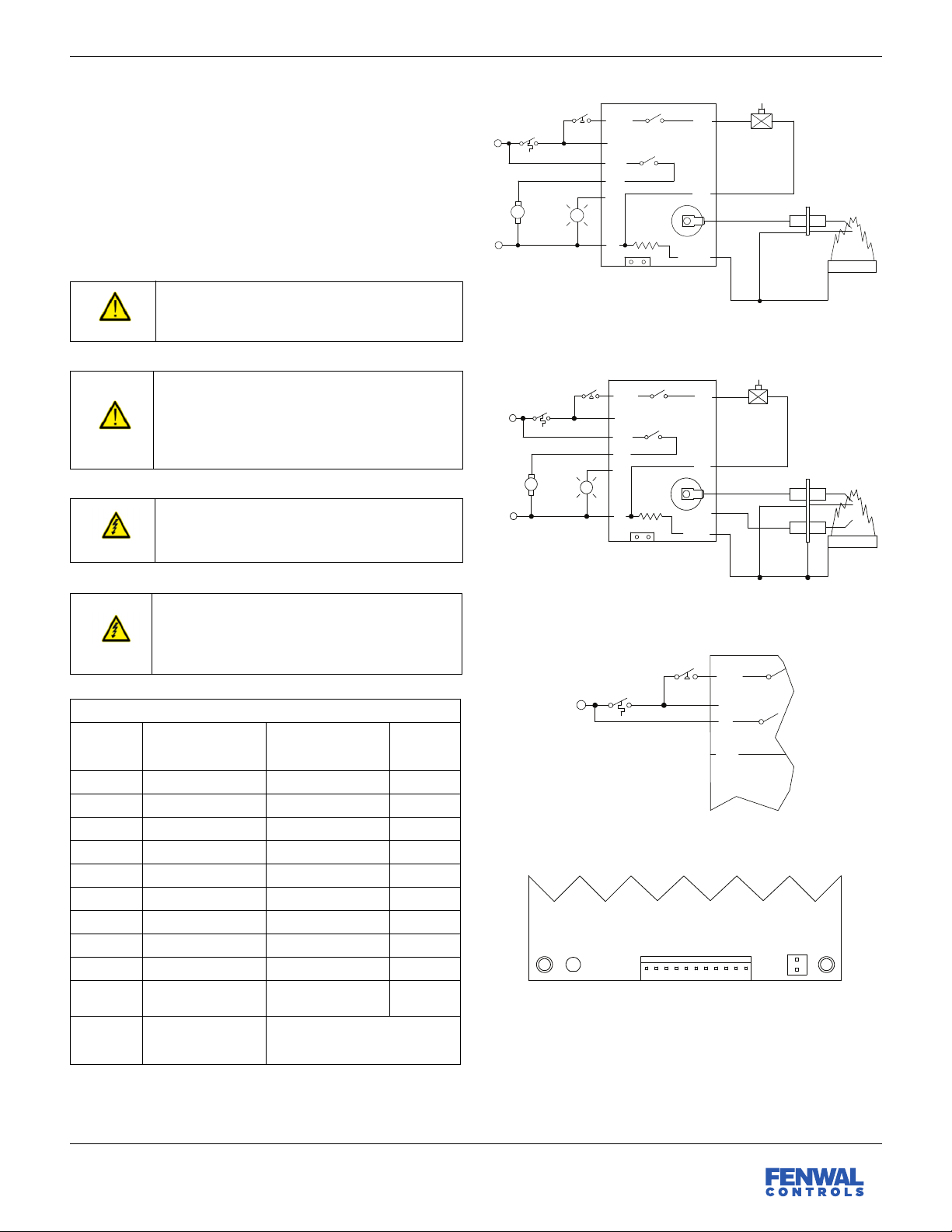
Start Up - Heat Mode
When a call for heat is received from the thermostat supplying
120 VAC to TH, the control will check the pressure switch for
normally open contacts. The inducer blower is then energized.
Once the pressure switch contacts close, a pre-purge delay
begins. Following the pre-purge period, the gas valve is
energized and sparking commences for the Trial for Ignition
(TFI) period.
When flame is detected during the TFI, the sparking process is
terminated and the gas valve and inducer blower remain
energized. The thermostat, pressure switch and burner flame
are constantly monitored to ensure proper system operation.
When the thermostat is satisfied and the demand for heat
terminates, the gas valve is immediately de-energized. The
control verifies the loss of flame signal and initiates an optional
post-purge period before de-energizing the inducer blower.
Failure to Light - Lockout
SINGLE TRIAL MODEL
Should the burner fail to light, or a flame is not detected during
the TFI period, the gas valve will de-energize and the control will
go into lockout. The inducer blower will turn off following the
optional post-purge period. The LED will indicate the fault code
for ignition lockout.
MULTI TRIAL MODEL
Should the burner fail to light or the flame is not detected during
the TFI period, the gas valve will de-energize. The control will
then go through an inter-purge delay before an additional
ignition attempt. The control attempts two additional ignition
trials before de-energizing the gas valve and entering lockout.
The inducer blower will turn off following the optional post-
purge period. The LED will indicate the fault code for ignition
lockout.
FLAME FAILURE - RE-IGNITION MODE
If the established flame signal is lost while the burner is
operating, the control will respond within 0.8 seconds by
immediately energizing the spark for the TFI period in an
attempt to relight the flame. If the burner does not light within
the TFI, the gas valve will immediately de-energize and single
try models will enter lockout. On multi-try models, a new TFI
sequence will begin after an inter-purge delay. Multi-try models
perform two additional attempts to light the burner. If the
burner relights, normal operation resumes. If the burner does
not relight, the control will enter lockout and the inducer blower
will turn off following the optional post-purge period.
FLAME FAILURE - RECYCLE MODE
With the “Recycle After Loss of Flame" option, upon loss of
flame, the gas valve is de-energized and the control proceeds to
inter-purge before attempting to relight the flame. Multi-try
models permit three tries for ignition including inter-purges. If
the burner relights, normal operation resumes. If the burner
does not relight, the control will enter lockout and the inducer
blower will turn off following the optional post-purge period.
Lockout Recovery
Recovery from lockout requires a manual reset by either
resetting the thermostat, or removing 120 VAC for a period of 5
seconds. On models with automatic reset, if the thermostat is
still calling for heat after one hour, then the control will
automatically reset and attempt to ignite the burner.
Combustion Airflow Fault
Combustion airflow is continually monitored during an ignition
sequence by the pressure switch (PSW). If during the initial call
for heat, the switch contacts are in the closed position for 30
seconds, without the inducer blower being energized, the LED
will indicate an airflow fault and remain in this mode with the
inducer blower off. If the pressure switch contacts later open
while there is still a call for heat, the control will begin the pre-
purge period followed by a normal ignition sequence.
If the pressure switch remains open for more than 30 seconds
after the inducer blower output (L1 & IND) is energized, the LED
will indicate an airflow fault and the control will remain in this
mode with the inducer blower on, waiting for the pressure
switch to close. When proper airflow is detected at the pressure
switch input (PSW) the control will begin the pre-purge period
followed by a normal ignition sequence.
If the airflow signal is lost while the burner is firing, the control
will immediately de-energize the gas valve and the LED will
indicate an airflow fault. The inducer blower will remain on for
the post-purge period and the control continues to monitor the
PSW input waiting for airflow to return. If proper airflow is
detected during the post-purge period, a normal ignition
sequence will begin with the pre-purge period. Otherwise, the
control will remain in an airflow fault as indicated by the LED
with the inducer blower off.