Eyevision EV-DMR18S Manuel utilisateur
1 2 3
654
7 8 9
#0
*
RF CARD
Please read this manual carefully before using the product you purchase, and keep it well for future use.
We reserve the right to modify the specification in this manual at any time without notice.
EV-DMR18S-DMR18SF-v01-04 20220131
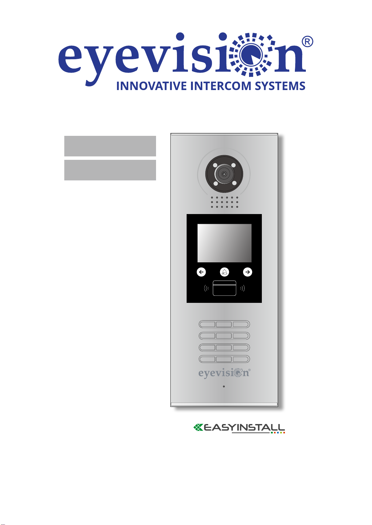
Door Station
User Manual
EV-DMR18S
EV-DMR18SF

1.Parts and Functions
2. Terminal Descriptions
Camera Lens
Night View LED
Speaker
Adjustable Camera
Connectiong Port
With rainy cover
350 mm
128 mm
1 2 3
654
7 8 9
#0
*
LCD Screen
ID Card Window
Digital Keypad
Microphone
12
3
Touch Key
RF CARD
L1
T/R -
CN-LK
T/R+
J/KMB JP-LK
SD Card Slot
Bus
EB+
EB-
N.O
LK+
LK-
+12V
L2
12
3
12
3
+12V:
• 12VDC power output.
LK-(GND):
• Power ground.
LK+(COM):
• Common contact of the Relay .
NO.:
• Normally open contact of the Relay(refer to DT technical guide for Lock connection
• detail informations).
EB+:
• Exit button connection port.
EB-:
• Exit buton connection port.
JP-LK:
• For electronic lock safety type setting(refer to Door Station Lock Connections).
T/R-:
• USB-RS485 communication terminal negative.
T/R+:
• USB-RS485 communication terninal positive.
Bus( ):
• L1,L2 non-polarity bus line.

3.Door Station Mounting
1 2
4 5 6
Drill holes in the wall to match the size of
screws and attach the rainy cover to the wall.
Attach screws to fix the
metal box
Attach the unit to the rainy
cover correctlly
The last view for all mounting
The view for rainy
cover after mounted
Adjust the camera angle and attach the
Camera
metal to the panel and wire correctly.
angle
3
Surface mounting

1 2 3
4
7
5 6
Drill a hole and attach the
rainy cover to it
Attach screws to fix the
metal box
Attach the unit to the rainy
cover correctlly
Attach the baffle to protect
the unit from droping
The last view for all mounting
The view for rainy
cover after mounted
Adjust the camera angle and attach the
Camera
metal to the panel and wire correctly.
angle
147mm
395
m
m
42mm
RF CARD
Flush mounting

Code=0
OFF ON
OFF ON
DBC4A1
A B C D
DBC4A1
A B C D
Impedance
switch
Impedance
switch
NOTE:Here we take DT47M(the monitor) for example.
Code=2
Code=1
Code=3
Code=28
Code=30
Code=29
Code=31
1 2 3
654
7 8 9
#0
*
RF CARD
DPS(V2)HDR-30-24
PC7 / PC7H
4. System Connection
ID Code=0

5. Door Lock Connections
1. Internal Power Supply Mode
Use the power of the system to supply for the electronic lock, so that the lock can be
connected to the door station directly, without an additional power supply for the electronic lock.
Note that the door station can only output 12Vdc power, therefore the kind of lock is limited.
• The rated power of the lock must be less than 12Vdc 300mA when using internal power
supply mode
• The GND must connect to the negative of the lock, and the COM connect to the positive .
• Jumper set to 1-2 position for Power-off-to-Unlock safety type(Normally closed mode);
set to 2-3 position for Power-on-to -Unlock type(Normally open mode ).
• If different unlocking time is needed to be configured, change the Unlock Timing on
door station.(In debug state, press [1 #] --> [1] Installer Setup--> [2]Unlock Timing)
JP_LK
12V 300mA
Jumper set to 2-3 position
+
-+12V
LK - (GND)
LK+(COM)
N.O.
EB+
EB -
1
2
3
set to Normally open on the
Unlock Relay mode
A. Connection for Power-on-to-Unlock type:
12V 300mA
Jumper set to 1-2 position
+12V
LK - (GND)
LK+(COM)
N.O.
EB+
EB -
+
-
set to Normally Closed on the
Unlock Relay mode
JP_LK
1
2
3
B. Connection for Power--off-to-Unlock type:

+
+
-
-
+12V
LK - (GND)
LK+(COM)
N.O.
EB+
EB -
Remove the Jumper
set to Normally Open on the
Unlock Relay mode (default)
JP_LK
1
2
3
Note: Cut off this line when
using external power supply
+12V
LK - (GND)
LK+(COM)
N.O.
EB+
EB -
Remove the Jumper
set to Normally Closed on the
Unlock Relay mode
+
+
-
-
JP_LK
1
2
3
Note: Cut off this line when
using external power supply
2. External Power Supply Mode
C. Connection for Power-to-Unlock type:
D. Connection for Power--off-to-Unlock type:
When the electronic lock is over 12 Vdc, additional power supply for the lock is needed.
• The power supply for the lock must be less than 48Vdc 1.5A.
• The Jumper must be removed when using external power supply. The default setting is
Power-on-to-Unlock type , if use Power-off-to-Unlock type, (Normally open mode)
change the Unlock Relay mode to .Normally closed mode
• If different unlocking time is needed to be configured, change the on Unlock Timing
door station.(In debug state, press [1 #] --> [1] Installer Setup--> [2]Unlock Timing)

6. Door Station Configurations
1. About room code(address):
Room Code(also called room address) is a code assigned to each monitor, to identify different
monitors; each monitor have a unique room code in one buidling.The room Code is stored in
each Monitor’s inner EEPROM memory, and does not lose even the monitor is power off.
2. About Debug State:
The Debug State is your starting point for using all the applications on DMR18S.
When Door Station is in
standby, press '#' key
Press "2#" key to exit out the debug state.
input '9008', then input the
Admin Code.(66666666 by
default)
Debug State menu is launched
[ 9 0 0 8 ]
Please Input Password
1 2 3
654
7 8 9
#0
*
RF CARD
> > D e b u g S t a t e < <
1 - # To o l s
0 - # R e d i a l
2 - # E x i t s
3. About Debug Tools:
During working at Debug State,press "1#" to enter tools page,Debug Tools overviews is
shown as below:
1 . I n s t a l l e r S e t u p
2 . S e t u p
3 . C a r d M a n a g e
4 . O n l i n e M o n i t o r s
5 . O n l i n e D e v i c e s
6 . V o l t a g e M e a s u r e
Pres NO.
Tools
to select
*Back
> > D e b u g S t a t e < <
0 - # R e d i a l
2 - # E x i t s
1 - # To o l s

Item Submenu
1. Installer Setup
1. ID Code [0]
2. Unlock Timing [01]
3. Unlock Output [0]
4. Monitor Timing [600]
5. Doorplate Mode [1]
6. Waiting Timing [040]
7. Talking Timing [090]
8. Installer Code ...
9. Default ...
2. Setup
1. Language [0]
2. Tone Select [01]
3. Tone Volume [3]
4. Unlock Code [1111]
5. Work Mode [0]
6. Clock ...
7. Setup Code ...
8. About ...
9. Default ...
3. Card Manage
1. Add Card ...
2. Delete By Card
3. Delete By M.code
4. Cards Information
5. Format
4. Online Monitors To search the online monitors,input the monitor code
number to search
5. Online Devices To search the online door stations. Max. 4 door station
can be searched
6. Voltage Measure To check the voltage of the monitor,note that the
monitor must be online.
Table 1:

Basic Tools Detail:
Item Description Factory
set
ID Code
If only one door station is installed in this building, set to
0;
If multi door stations are installed, primary door station
must be set to 0, and other slave door stations must
be set from 1 to 3. Note that max. 4 door stations are
available in one building
[0]
Single
Unlock Timing To set the time that how long the door keeps open when
door is released. Range from 01 to 99 seconds.
[01]
1 seconds
Unlock Output
To set the unlock mode to match the corresponding lock.
Range from 0 to 1.
0:Power-on-to-Unlock Mode(Normally Open Mode)
1:Power-off-to-Unlock Mode(Normally Closed Mode)
0
Monitor Timing To show the monitor time,Range from 6s to 600s 600s
Auto Call:
Doorplate Mode Range from 0 to 1. 0:after a complete input
the call codes, automatically dialing; 1:required to input
"#" to confirm dialing after input a complete call codes.
Building No.: 0~4 digit for the Building No., 0 means
without Building No. the door station will be only call to
local monitor.
Room No.: 2~4 digit for the Room No., at least 2 digit
for the Room No. to call.
Input No.: 2~8 maximum digit for input codes, at least
2 digit.
Call Mode: Reserve, always set it to 2.
[1]
Waiting Timing To show the calling wait time,Range from 6s to 600s 40s
Talking Timing To show the limitation time of talking, Range from 6s to
600s 90s
Installer Code ... To change door station administrator code [66666666]
Default ...
Note this operation is irreversible. Once restore is
activated, all parameters will return to factory default
setting except the information of access card.
Table 2(Installer Setup):
Ce manuel convient aux modèles suivants
1
Table des matières
Autres manuels Eyevision Système d'interphone

Eyevision
Eyevision EV-D301 Manuel utilisateur

Eyevision
Eyevision EV-D298F Series Manuel utilisateur

Eyevision
Eyevision EV-TRUWL7-KP22 Manuel utilisateur

Eyevision
Eyevision EV-IP-KP22 Manuel utilisateur

Eyevision
Eyevision Intelli Series Manuel utilisateur

Eyevision
Eyevision WF-D02S Manuel utilisateur

Eyevision
Eyevision EV-V4L Manuel utilisateur

Eyevision
Eyevision EV-H298 Manuel utilisateur


