Evco Vcolor 318 M Guide de l'utilisateur

EVCO S.p.A. Vcolor 378 | Installer manual ver. 1.0 | Code 144VC378E104
Page 1 o 50
Vcolor 378
Controllers for bread and pizza deck ovens
ENGLISH
INST LLER M NU L ver. 1.0
CODE 144VC378E104

EVCO S.p.A. Vcolor 378 | Installer manual ver. 1.0 | Code 144VC378E104
Page 2 o 50
Important
Read this document care ully be ore installation and be ore
using the device and take all the prescribed precautions. Keep
this document with the device or uture consultation.
Only use the device in the ways described in this document. Do
not use the device as a sa ety device.
Disposal
The device must be disposed o according to local regulations
governing the collection o electrical and electronic equipment.

EVCO S.p.A. Vcolor 378 | Installer manual ver. 1.0 | Code 144VC378E104
Page 3 o 50
Contents
1 INTRODUCTION .................................. 4
1.1 Product description ............................. 4
1.2 Models available and technical eatures . 5
2 INSTALLATION ................................... 8
2.1 Format eatures .................................. 8
2.2 Measurements in mm (inches) and
installation ......................................... 8
2.3 Installation precautions ..................... 10
3 ELECTRICAL CONNECTION ................. 11
3.1 Vcolor 378M electrical connection ....... 11
3.2 Vcolor 378L electrical connection ........ 13
3.3 Vcolor 378M electrical connection in multi-
base mode ....................................... 15
3.4 Vcolor 378L electrical connection in multi-
base mode ....................................... 15
3.5 Electrical connection with a motorised
venting solenoid valve ....................... 16
3.6 Precautions or electrical connection ... 16
4 FIRST-TIME USE ............................... 17
4.1 First-time use .................................. 17
5 USER INTERFACE ............................. 18
5.1 Initial in ormation ............................. 18
5.2 Splash screen .................................. 18
5.3 STAND-BY screen ............................. 18
5.4 ON screen ....................................... 18
5.5 Recipe book ..................................... 21
5.6 Locked display ................................. 23
6 “WEEKLY PROGRAMMED SWITCH-ON"
FUNCTION ....................................... 23
6.1 Initial in ormation ............................. 23
6.2 Setting and activating the "Weekly
programmed switch-on" unction ........ 23
7 MANAGING LOADS ........................... 24
7.1 Initial in ormation ............................. 24
7.2 Temperature regulation ..................... 24
7.3 Steamer management ....................... 25
7.4 Suction hood management ................ 26
7.5 Buzzer management ......................... 26
7.6 Electronics compartment an .............. 26
7.7 Stand-by/on relay management ......... 26
7.8 Sound relay management .................. 26
7.9 Type 1 or 2 burner ault reset ............ 26
8 CONFIGURATION .............................. 27
8.1 Initial in ormation ............................. 27
8.2 Setting the date and time .................. 27
8.3 List o alarms ................................... 27
8.4 Internal values ................................. 27
8.5 Service ............................................ 27
8.6 Languages ....................................... 27
8.7 Oven cleaning cycle .......................... 27
8.8 Display cleaning ............................... 28
8.9 USB ................................................ 28
9 MULTI-BASE CONFIGURATION ........... 28
10 LIST OF CONFIGURATION
PARAMETERS ................................... 30
11 ALARM MANAGEMENT ....................... 38
12 CONNECTIVITY ................................. 40
12.1 Initial in ormation ............................. 40
12.2 EPoCA cloud plat orm ........................ 41
13 USING THE USB PORT ....................... 42
13.1 Initial in ormation ............................. 42
13.2 Uploading the recipe settings ............. 42
13.3 Downloading the recipe settings ......... 42
13.4 Uploading the settings in the con iguration
parameters ...................................... 42
13.5 Downloading the settings in the
con iguration parameters ................... 42
13.6 Uploading CSV iles to personalise the
graphics, recipes and languages ......... 42
14 ACCESSORIES .................................. 43
14.1 Sa ety trans ormer ............................ 43
14.2 Non-optoisolated RS-485/USB serial
inter ace .......................................... 43
14.3 USB plug or panel installation ............ 43
14.4 Connecting cables ............................. 43
14.5 Buzzer expansion.............................. 44
14.6 4GB USB lash drive .......................... 44
14.7 EVlinking Wi-Fi RS-485 module .......... 44
14.8 EV3 Web gateway ............................. 44
15 TECHNICAL SPECIFICATIONS ............. 45
15.1 Technical data .................................. 45

EVCO S.p.A. Vcolor 378 | Installer manual ver. 1.0 | Code 144VC378E104
Page 4 o 50
1INTRODUCTION
1.1 Product description
Vcolor 378 is a controller or electric bread and pizza deck ovens with a remote touch-screen user inter ace in 5- or 7-inch glass which
its in per ectly with the design o the unit. It can control up to 5 levels through an RS-485 network o power boards connected to a single
user inter ace.
It manages steam (generation, injection and venting) in both automatic and manual mode and independently regulates the power and
temperature o the top, loor and ront heaters. Being able to control the temperature o the ront heater is particularly important or
certain baked goods.
The controller has an oven cleaning unction which uses pyrolysis, a sel -cleaning mechanism that does not require chemical detergents
as ood residue is oxidised at high temperature.
The controller can save up to 99 recipes; each recipe can have up to 8 phases, each with independent settings or duration, temperature,
steam injection cycles, venting and suction. Recipes can be compiled in an ODS ile (complete with pictures in BMP or GIF ormat) and
uploaded to the controller using a USB lash drive, thanks to the innovative programmable plat orm which allows users to customise their
recipes and add new languages. Recipes can also be altered, overwritten and saved directly rom the display and two di erent recipes
can be switched on and o or every day o the week.
Users can interact remotely with their equipment and start up/stop working cycles using the EPoCA® cloud plat orm with Wi-Fi or Ethernet
connectivity (which also enables alternative or parallel control through MODBUS TCP). For more details, compare all the connectivity
options in the Technical Data table and consult the Management and Monitoring Products/Systems and the Connectivity Products/Devices
sections o our website.

EVCO S.p.A. Vcolor 378 | Installer manual ver. 1.0 | Code 144VC378E104
Page 5 o 50
1.2 Models available and technical features
The table below shows the technical eatures o the models available.
Vcolor 378 M & L
with J/K thermocouples
Vcolor 378 M & L
with Pt 100 2 wires
Power supply
Control module 12 Vac 12 Vac
User inter ace Powered by the control module Powered by the control module
nalogue inputs (J/K or Pt100)
Top probe (activated as chamber probe i
regulation is by single analogue input with
power distributed between the top and loor)
J/K thermocouples Pt 100 2 wires
Floor probe (deactivated i regulation is by
single analogue input) J/K thermocouples Pt 100 2 wires
Steam probe J/K thermocouples Pt 100 2 wires
Front probe J/K thermocouples Pt 100 2 wires
Digital inputs (for NO/NC contact)
Power consumption (230 Vac) • •
Thermal switch (230 Vac) • •
Type 1/2 burner ault (230 Vac) • •
Door switch • •
Enable steam injection • •
Switch o device • •
Energy saving • •
Digital outputs (electro-mechanical
relays; res. @ 250 Vac)
Con igurable k1 (de ault top heaters) 5 A 5 A
Con igurable k2 (de ault stand-by/on) 5 A 5 A
Con igurable k3 (de ault loor heater) 5 A 5 A
Con igurable k4 (de ault loor ront heater) 5 A 5 A
Con igurable k5 (de ault chamber light) 5 A 5 A
Con igurable k6 (de ault venting) 5 A 5 A

EVCO S.p.A. Vcolor 378 | Installer manual ver. 1.0 | Code 144VC378E104
Page 6 o 50
Con igurable k7 (de ault steam generation) 5 A 5 A
Con igurable k8 (de ault steam injection) 5 A 5 A
Con igurable k9 (de ault suction hood) 8 A 8 A
Con igurable k10 (de ault electronics
compartment an) 5 A 5 A
Con igurable k11 (de ault sound) 5 A 5 A
Con igurable k12 (de ault reset o burner ault
1/2) 5 A 5 A
Con igurable k13 (de ault top ront heater) 8 A 8 A
Communications ports
RS-485 MODBUS • •
USB • •
Connectivity
RS-485 MODBUS RTU (built-in) • •
Wi-Fi EPoCA/MODBUS TCP (optional through
the EVlinking Wi-Fi module powered by
controller)
• •
Ethernet EPoCA/MODBUS TCP (optional
through EV3 Web gateway) • •
Other features
"Cooking timer" unction • •
"Rapid heating" unction • •
Clock • •
Alarm buzzer • •
Independent management o the power
delivered to top and loor • •
Independent management o the top and loor
temperatures • •
"Weekly programmed switch-on" unction • •
"Programmes" unction • •
"Energy-saving" unction • •

EVCO S.p.A. Vcolor 378 | Installer manual ver. 1.0 | Code 144VC378E104
Page 7 o 50
For more in ormation, see section 1515 “TECHNICAL SPECIFICATIONS”.
The table below lists the purchasing codes o the available models:
Purchasing codes
With J/K thermocouples
Vcolor 378 M (control module + 5” user interface kit):
EVCMC37DJ2E ( lush it installation)
EVCMC37DJ2EF (semi-recessed installation)
Vcolor 378 L (control module + 7” user interface kit):
EVCLC37DJ2E ( lush it installation)
EVCLC37DJ2EF (semi-recessed installation)
Vcolor 378 M&L (additional control modules)
EVCLP37DJ2E
With Pt 100 2 wires
Vcolor 378 M (control module + 5” user interface kit):
EVCMC37DC2E ( lush it installation)
EVCMC37DC2EF (semi-recessed installation)
Vcolor 378 L (control module + 7” user interface kit):
EVCLC37DC2E ( lush it installation)
EVCLC37DC2EF (semi-recessed installation)
Vcolor 378 M&L (additional control modules)
EVCLP37DC2E
For more models, contact the EVCO sales network.

EVCO S.p.A. Vcolor 378 | Installer manual ver. 1.0 | Code 144VC378E104
Page 8 o 50
2ME SUREMENTS ND INST LL TION
2.1 Format features
The control module is available in a split version with an open rame board. User inter aces are available in 5 or 7-inch versions or vertical
operation and have capacitive colour TFT touch-screen graphic displays.
2.2 Measurements and installation of the control module
Measurements are indicated in mm (in). Installation o the control module is on a lat sur ace with spacers.
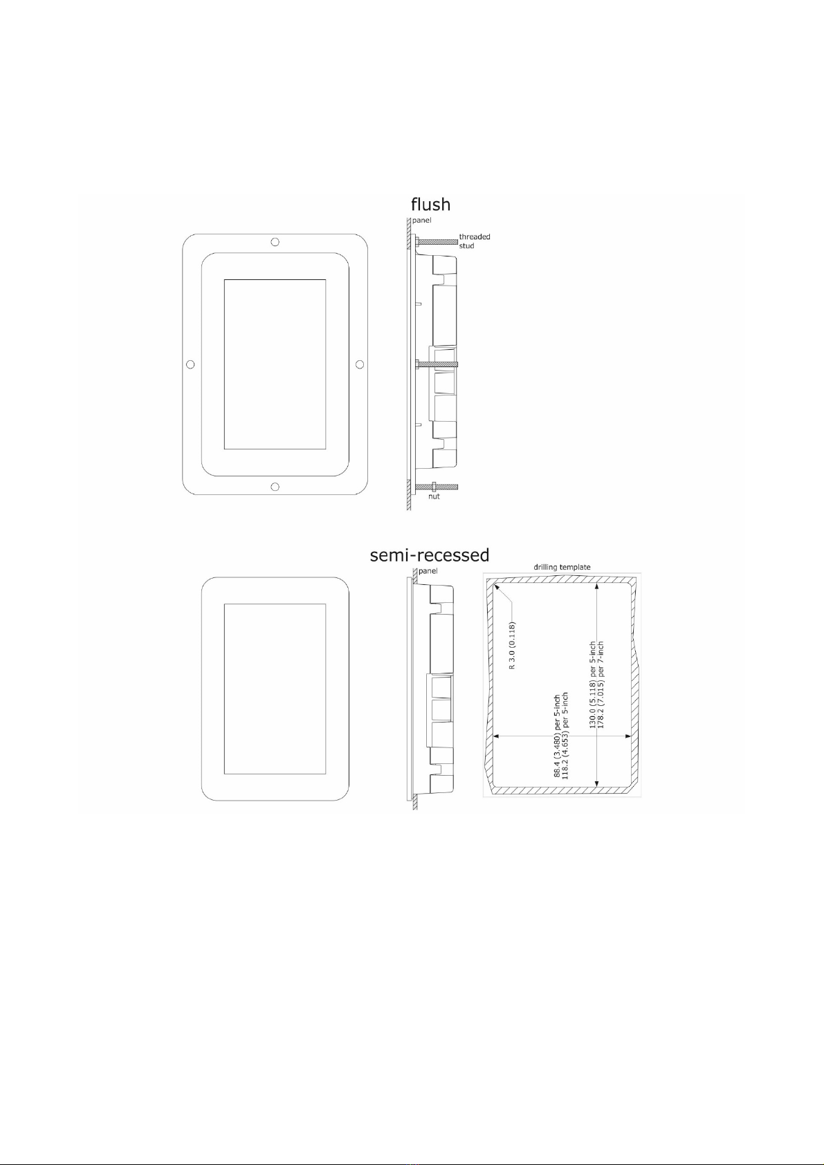
2.3 Measurements of the user interface
The user inter ace is available in the model or lush installation and in the model or semi-recessed rontal installation. Measurements
vary based on the model as shown below in mm (in).
Vcolor 378 M

EVCO S.p.A. Vcolor 378 | Installer manual ver. 1.0 | Code 144VC378E104
Page 9 o 50
Vcolor 378 L
EVCO S.p.A. Vcolor 378 | Installer manual ver. 1.0 | Code 144VC378E104
Page 10 o 50
2.4 Installation of the user interface
Depending on the model, installation can be:
-lush, rom behind the panel with threaded studs (not provided) welded to hold it in place;
-semi-recessed, rom the ront o the panel with spring clips to hold it in place.
2.5 Installation precautions
- Ensure that the working conditions or the device (operating temperature, humidity, etc.) are within the set limits. See section
15 “TECHNICAL SPECIFICATIONS”
- Do not install the device close to heat sources (heaters, hot air ducts, etc.), equipment with a strong magnetic ield (large
di users, etc.), in places subject to direct sunlight, rain, damp, excessive dust, mechanical vibrations or shocks
- Any metal parts close to the control module must be ar enough away so as not to compromise the sa ety distance
- In compliance with sa ety regulations, the device must be installed properly to ensure adequate protection rom contact with
electrical parts. All protective parts must be ixed in such a way as to need the aid o a tool to remove them
- Ensure that the thermocouple is properly insulated rom contact with metal parts or use already insulated thermocouples.
Autres manuels pour Vcolor 318 M
4
Ce manuel convient aux modèles suivants
1
Table des matières
Autres manuels Evco Système de contrôle


