Endress+Hauser Omnigrad M TR13 Manuel

TR13 with resistance insert (RTD)
TC13 with thermocouple insert (TC)
Application
• Universal range of application
• Measuring range:
– Resistance insert (RTD): –200 to 600 °C (–328 to 1 112 °F)
– Thermocouple (TC): –40 to 1 100 °C (–40 to 2 012 °F)
• Pressure range up to 100 bar (1 450 psi)
• Degree of protection: up to IP 68
Head transmitter
All Endress+Hauser transmitters are available with enhanced accuracy and reliability
compared to directly wired sensors. Easy customizing by choosing one of the
following outputs and communication protocols:
• Analog output 4 to 20 mA
• HART®
• PROFIBUS® PA
• FOUNDATION Fieldbus™
Your benefits
• High degree of flexibility thanks to modular design with standard terminal heads
as per DIN EN 50446 and customer-specific immersion lengths
• High degree of insert compatibility and design as per DIN 43772
• Extension neck to protect the head transmitter from overheating
• Fast response time with reduced/tapered tip form
• Types of protection for use in hazardous locations:
– Intrinsic Safety (Ex ia)
– Non-sparking (Ex nA)
Products Solutions Services
Technical Information
Omnigrad M TR13, TC13
Modular thermometer
TI01097T/09/EN/02.13
71226662

Omnigrad M TR13, TC13
2
Function and system design
Measuring principle Resistance thermometer (RTD)
These resistance thermometers use a Pt100 temperature sensor according to IEC 60751. The
temperature sensor is a temperature-sensitive platinum resistor with a resistance of 100 Ω at
0 °C (32 °F) and a temperature coefficient α = 0.003851 °C-1.
There are generally two different kinds of platinum resistance thermometers:
•Wire wound (WW): Here, a double coil of fine, high-purity platinum wire is located in a ceramic
support. This is then sealed top and bottom with a ceramic protective layer. Such resistance
thermometers not only facilitate very reproducible measurements but also offer good long-term
stability of the resistance/temperature characteristic within temperature ranges up to
600 °C (1 112 °F). This type of sensor is relatively large in size and it is comparatively sensitive to
vibrations.
•Thin film platinum resistance thermometers (TF): A very thin, ultrapure platinum layer,
approx. 1 μm thick, is vaporized in a vacuum on a ceramic substrate and then structured
photolithographically. The platinum conductor paths formed in this way create the measuring
resistance. Additional covering and passivation layers are applied and reliably protect the thin
platinum layer from contamination and oxidation, even at high temperatures.
The primary advantages of thin film temperature sensors over wire wound versions are their smaller
sizes and better vibration resistance. A relatively low principle-based deviation of the resistance/
temperature characteristic from the standard characteristic of IEC 60751 can frequently be observed
among TF sensors at high temperatures. As a result, the tight limit values of tolerance category A as
per IEC 60751 can only be observed with TF sensors at temperatures up to approx. 300 °C (572 °F).
For this reason, thin-film sensors are generally only used for temperature measurements in ranges
below 400 °C (932 °F).
Thermocouples (TC)
Thermocouples are comparatively simple, robust temperature sensors which use the Seebeck effect
for temperature measurement: if two electrical conductors made of different materials are connected
at a point, a weak electrical voltage can be measured between the two open conductor ends if the
conductors are subjected to a thermal gradient. This voltage is called thermoelectric voltage or
electromotive force (emf.). Its magnitude depends on the type of conducting materials and the
temperature difference between the "measuring point" (the junction of the two conductors) and the
"cold junction" (the open conductor ends). Accordingly, thermocouples primarily only measure
differences in temperature. The absolute temperature at the measuring point can be determined
from these if the associated temperature at the cold junction is known or is measured separately and
compensated for. The material combinations and associated thermoelectric voltage/temperature
characteristics of the most common types of thermocouple are standardized in the IEC 60584 and
ASTM E230/ANSI MC96.1 standards.

Omnigrad M TR13, TC13
3
Measuring system
A
°C
= 20-250V DC/AC
»50/60Hz
4...20 mA
24V DC / 30 mA
B
C
A0010442
1 Application example
A Mounted thermometer with head transmitter installed.
B RIA16 field display unit - The display unit records the analog measuring signal from the head transmitter and
shows this on the display. The LC display shows the current measured value in digital form and as a bar graph
indicating a limit value violation. The display unit is looped into the 4 to 20 mA circuit and gets the required
energy from there. More information on this can be found in the Technical Information (see "Documentation").
C Active barrier RN221N - The RN221N (24 V DC, 30 mA) active barrier has a galvanically isolated output for
supplying voltage to loop-powered transmitters. The universal power supply works with an input supply
voltage of 20 to 250 V DC/AC, 50/60 Hz, which means that it can be used in all international power grids.
More information on this can be found in the Technical Information (see "Documentation").
Design
E
1 2
3
4
5
66a 6b
IL
IL
L
10 mm
(0.4 in)
7
A0010444
2 Thermometer design
1 Insert with head transmitter mounted (example with 3 mm (0.12 in))
2 Insert with terminal block mounted (example with 6 mm (0.24 in))
3 Terminal head
4 Thermowell
5 Process conneciton: flange
6 Various tip shapes - detailed information see chapter "Tip shape":
6a Reduced or tapered for inserts with 3 mm (0.12 in)
6b Straight or tapered for inserts with 6 mm (0.24 in)
7 Jacket (protective sheath)
E Extension neck length
L Immersion length
IL Insertion length
Thermometers from the Omnigrad M TR13 and TC13 series have a modular design. The terminal
head is used as a connection module for the mechanical and electrical connection of the insert. The
position of the actual thermometer sensor in the insert ensures that it is mechanically protected. The
insert can be exchanged and calibrated without interrupting the process. Either ceramic terminal
blocks or transmitters can be fitted to the internal base washer.
Omnigrad M TR13, TC13
4
Measurement range •RTD: –200 to 600 °C (–328 to 1 112 °F)
• TC: –40 to 1 100 °C (–40 to 2 012 °F)
Performance characteristics
Operating conditions Ambient temperature
Terminal head Temperature in °C (°F)
Without mounted head transmitter Depends on the terminal head used and the cable gland or fieldbus
connector, see 'Terminal heads' section
With mounted head transmitter –40 to 85 °C (–40 to 185 °F)
With mounted head transmitter and
display
–20 to 70 °C (–4 to 158 °F)
Process pressure
The pressure values to which the actual thermowell can be subjected at the various temperatures and
maximum permitted flow velocity are illustrated by the figure below. Occasionally, the pressure
loading capacity of the process connection can be considerably lower. The maximum allowable
process pressure for a specific thermometer is derived from the lower pressure value of the
thermowell and process connection.
0
50
100
150
200
150 200 250 300 350 400
P (bar)
0
150 200 250 300 350 400
L (mm)
P (bar)
50
100
150
200
A B
L (in) 6810 12
0
700
2100
2900
P (PSI)
1400
14 166 810 12 14 16
0
700
2100
2900
P (PSI)
1400
L (mm)
L (in)
P ~ PN100max.
P ~ PN60max.
A0013494
3 Maximum permitted process pressure for tube diameter
A Medium water T = 50 °C (122 °F)
B Medium superheated steam at T = 400 °C (752 °F)
L Immersion length
P Process pressure
___ Thermowell diameter 9 x 1 mm (0.35 in)
- - - Thermowell diameter 12 x 2.5 mm (0.47 in)

Omnigrad M TR13, TC13
5
Note the limitation of the maximum process pressure to the flange pressure ratings indicated in
the following table.
Process
connection
Standard Max. process pressure
Flange EN1092-1 or ISO
7005-1
Depending on the flange pressure rating PNxx:
20, 40, 50 or 100 bar at 20 °C (68 °F)
ASME B16.5 Depending on the flange pressure rating 150 or 300 psi at
20 °C (68 °F)
JIS B 2220 Depending on the flange pressure rating 20K, 25K or 40K
DIN2526/7 Depending on the flange pressure rating PN40 at 20 °C (68 °F)
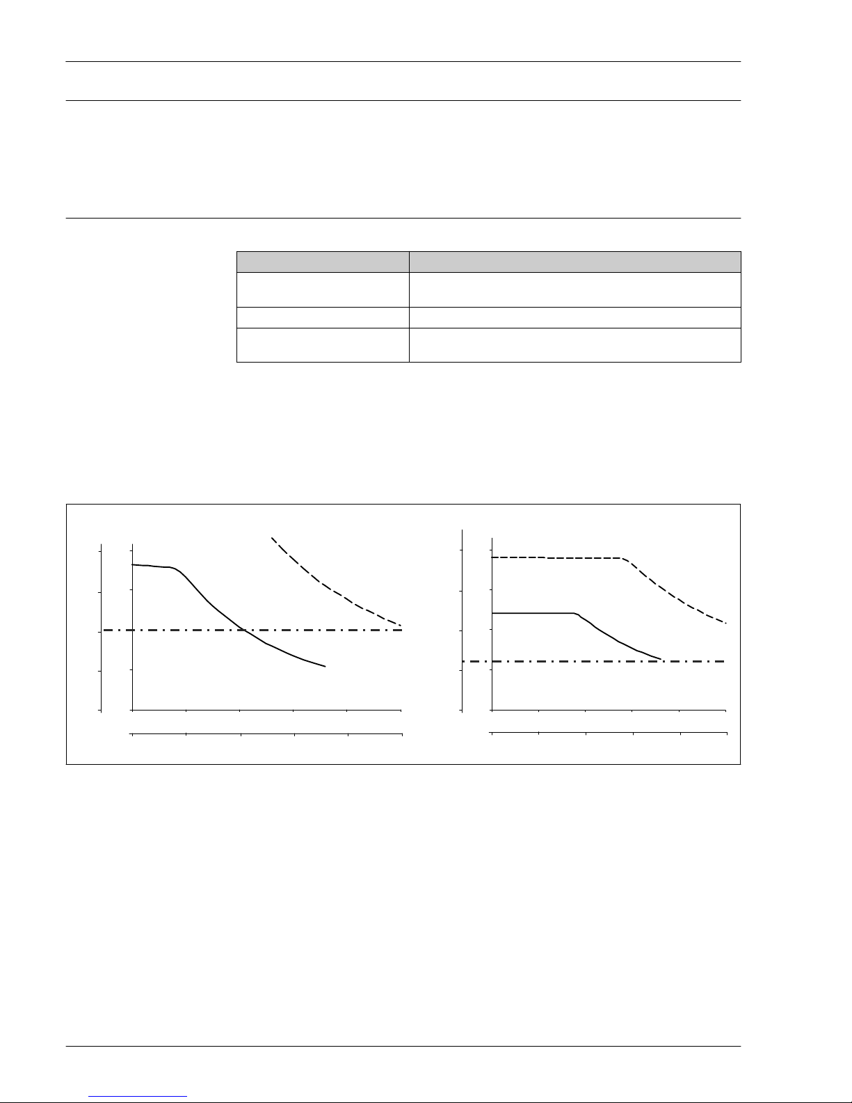
Maximum flow velocity
The highest flow velocity tolerated by the thermowell diminishes with increasing immersion length
exposed to the stream of the fluid. Detailed information may be taken from the figures below.
100 200 300 400 500
v (m/s)
A
100 200 300 400 500
v (m/s)
B
4812 16 20
4812 16
v (ft/s) v (ft/s)
L (mm)
0
10
20
30
40
50
60
70
80
90
L (in)
20
0
30
65
100
130
165
200
230
260
295
0
5
10
15
20
25
30
35
40
45
0
15
30
50
65
80
100
115
130
145
L (mm)
L (in)
50
2
50
2
A0008605
4 Flow velocity depending on the immersion length
A Medium water at T = 50 °C (122 °F)
B Medium superheated steam at T = 400 °C (752 °F)
L Immersion length
v Flow velocity
___ Thermowell diameter 9 x 1 mm (0.35 in)
- - - Thermowell diameter 12 x 2.5 mm (0.47 in)
Shock and vibration resistance
•RTD: 3G / 10 to 500 Hz according to IEC 60751
• TC: 4G / 2 to 150 Hz according to IEC 60068-2-6

Omnigrad M TR13, TC13
6
Accuracy RTD resistance thermometer as per IEC 60751
Class Max. tolerances (°C) Characteristics
Cl. AA, former 1/3
Cl. B
± (0.1 + 0.0017 · |t| 1))
A
AA
-200 -100 0 100 200 300 400 500 600°C
0.5
1.0
1.5
2.0
B
2.5
3.0
- 0.5
- 1.0
- 1.5
- 2.0
- 2.5
- 3.0
B
A
AA
Max. deviation (°C)
Max. deviation (°C)
A0008588-EN
Cl. A ± (0.15 + 0.002 · |t| 1))
Cl. B ± (0.3 + 0.005 · |t| 1))
Temperature ranges for compliance with the
tolerance classes
Wire wound
sensor (WW):
Cl. A Cl. AA
–100 to
+450 °C
–50 to +250 °C
Thin-film version
(TF):
Cl. A Cl. AA
• Standard
• iTHERM®
StrongSens
–30 to +300 °C
–30 to +300 °C
0 to +150 °C
0 to +200 °C
1) |t| = absolute value °C
In order to obtain the maximum tolerances in °F, the results in °C must be multiplied by a factor
of 1.8.
Permissible deviation limits of thermoelectric voltages from the standard characteristic for
thermocouples as per IEC 60584 or ASTM E230/ANSI MC96.1:
Standard Type Standard tolerance Special tolerance
IEC 60584 Class Deviation Class Deviation
J (Fe-CuNi) 2 ±2.5 °C (–40 to 333 °C)
±0.0075 |t| 1) (333 to 750 °C)
1 ±1.5 °C (–40 to 375 °C)
±0.004 |t| 1) (375 to 750 °C)
K (NiCr-NiAl) 2 ±2.5 °C (–40 to 333 °C)
±0.0075 |t| 1) (333 to 1 200 °C)
1 ±1.5 °C (–40 to 375 °C)
±0.004 |t| 1) (375 to 1 000 °C)
1) |t| = absolute value °C
Standard Type Standard tolerance Special tolerance
ASTM E230/ANSI
MC96.1
Deviation, the larger respective value applies
J (Fe-CuNi) ±2.2 K or ±0.0075 |t| 1) (0 to 760 °C) ±1.1 K or ±0.004 |t| 1)
(0 to 760 °C)
K (NiCr-NiAl) ±2.2 K or ±0.02 |t| 1) (–200 to 0 °C)
±2.2 K or ±0.0075 |t| 1)
(0 to 1 260 °C)
±1.1 K or ±0.004 |t| 1)
(0 to 1 260 °C)
1) |t| = absolute value °C

Omnigrad M TR13, TC13
7
Response time Calculated at an ambient temperature of approx. 23 °C by immersing in running water (0.4 m/s flow
rate, 10 K excess temperature):
Complete assembly:
Thermometer
type
Diameter t(x) Reduced tip Tapered tip Straight tip
Resistance
thermometer
(measuring probe
Pt100, TF/WW)
9 mm (0.35 in) t50 7.5 s 11 s 18 s
t90 21 s 37 s 55 s
11 mm (0.43 in) t50 7.5 s not available 18 s
t90 21 s not available 55 s
12 mm (0.47 in) t50 not available 11 s 38 s
t90 not available 37 s 125 s
Thermo-
meter type
Diameter t(x) Grounded Ungrounded
Reduced
tip
Tapered
tip
Straight
tip
Reduced
tip
Tapered
tip
Straight
tip
Thermo-
couple
9 mm
(0.35 in)
t50 5.5 s 9 s 15 s 6 s 9.5 s 16 s
t90 13 s 31 s 46 s 14 s 33 s 49 s
11 mm
(0.43 in)
t50 5.5 s not
available
15 s 6 s not
available
16 s
t90 13 s not
available
46 s 14 s not
available
49 s
12 mm
(0.47 in)
t50 not
available
8.5 s 32 s not
available
9 s 34 s
t90 not
available
20 s 106 s not
available
22 s 110 s
Response times for insert without transmitter.

Omnigrad M TR13, TC13
8
Tested in accordance with IEC 60751 in flowing water (0.4 m/s at 30 °C):
Insert:
Sensor type Diameter ID Response time Thin film (TF)
iTHERM® StrongSens 6 mm (0.24 in) t50 <3.5 s
t90 <10 s
TF Sensor
3 mm (0.12 in) t50 2.5 s
t90 5.5 s
6 mm (0.24 in) t50 5 s
t90 13 s
WW Sensor
3 mm (0.12 in) t50 2 s
t90 6 s
6 mm (0.24 in) t50 4 s
t90 12 s
Thermocouple (TPC100)
grounded
3 mm (0.12 in) t50 0.8 s
t90 2 s
6 mm (0.24 in) t50 2 s
t90 5 s
Thermocouple (TPC100)
ungrounded
3 mm (0.12 in) t50 1 s
t90 2.5 s
6 mm (0.24 in) t50 2.5 s
t90 7 s
Response time for the sensor assembly without transmitter.
Insulation resistance •RTD:
Insulation resistance according to IEC 60751 > 100 MΩ at 25 °C between terminals and sheath
material measured with a minimum test voltage of 100 V DC
• TC:
Insulation resistance according to IEC 1515 between terminals and sheath material with a test
voltage of 500 V DC:
– > 1 GΩ at 20 °C
– > 5 MΩ at 500 °C
Dielectric strength Tested at a room temperature for 5 s:
•6: ≥1 000 V DC between terminals and insert sheath
• 3: ≥250 V DC between terminals and insert sheath
Self heating RTD elements are passive resistances that are measured using an external current. This
measurement current causes a self-heating effect in the RTD element itself which in turn creates an
additional measurement error. In addition to the measurement current, the size of the measurement
error is also affected by the temperature conductivity and flow velocity of the process. This self-
heating error is negligible when an Endress+Hauser iTEMP® temperature transmitter (very small
measurement current) is connected.
Calibration Endress+Hauser provides comparison temperature calibration from
–80 to +1 400 °C (–110 to +2 552 °F) based on the International Temperature Scale (ITS90).

Omnigrad M TR13, TC13
9
Calibrations are traceable to national and international standards. The calibration certificate is
referenced to the serial number of the thermometer. Only the insert is calibrated.
Insert:
⌀6 mm (0.24 in) and 3 mm (0.12 in)
Minimum insertion length of insert in mm (in)
Temperature range without head transmitter with head transmitter
–80 to –40 °C (–110 to –40 °F) 200 (7.87)
–40 to 0 °C (–40 to 32 °F) 160 (6.3)
0 to 250 °C (32 to 480 °F) 120 (4.72) 150 (5.91)
250 to 550 °C (480 to 1 020 °F) 300 (11.81)
550 to 1 400 °C (1 020 to 2 552 °F) 450 (17.72)
Material Extension neck, thermowell and insert
The temperatures for continuous operation specified in the following table are only intended as
reference values for use of the various materials in air and without any significant compressive load.
The maximum operation temperatures are reduced considerably in some cases where abnormal
conditions such as high mechanical load occur or in aggressive media.
Material name Short form Recommended max.
temperature for
continuous use in air
Properties
Wetted parts
AISI 316L/
1.4404
1.4435
X2CrNiMo17-12-2
X2CrNiMo18-14-3
650 °C (1 202 °F) 1) • Austenitic, stainless steel
• High corrosion resistance in general
• Particularly high corrosion resistance
in chlorine-based and acidic, non-
oxidizing atmospheres through the
addition of molybdenum (e.g.
phosphoric and sulfuric acids, acetic
and tartaric acids with a low
concentration)
• Increased resistance to intergranular
corrosion and pitting
• Compared to 1.4404, 1.4435 has even
higher corrosion resistance and a
lower delta ferrite content
AISI 316Ti/
1.4571
X6CrNiMoTi17-12-2 700 °C (1 292 °F) 1) • Properties comparable to AISI316L
• Addition of titanium means increased
resistance to intergranular corrosion
even after welding
• Broad range of uses in the chemical,
petrochemical and oil industries as
well as in coal chemistry
• Can only be polished to a limited
extent, titanium streaks can form
Inconel600/
2.4816
NiCr15Fe 1 100 °C (2 012 °F) • A nickel/chromium alloy with very
good resistance to aggressive,
oxidizing and reducing atmospheres,
even at high temperatures
• Resistance to corrosion caused by
chlorine gases and chlorinated media
as well as many oxidizing mineral and
organic acids, sea water etc.
• Corrosion from ultrapure water
• Not to be used in sulfur-containing
atmospheres

Omnigrad M TR13, TC13
10
Material name Short form Recommended max.
temperature for
continuous use in air
Properties
Hastelloy
C276/2.4819
NiMo16Cr15W 1 100 °C (2 012 °F) • A nickel-based alloy with good
resistance to oxidizing and reducing
atmospheres, even at high
temperatures
• Particularly resistant to chlorine gas
and chloride as well as to many
oxidizing mineral and organic acids
Jacket
PTFE (Teflon) Polytetrafluorethylen 200 °C (392 °F) • Resistant to almost all chemicals
• High temperature stability
PVDF Polyvinylidene fluoride 80 °C (176 °F) • High stability
• A high creepage stability under
continuous demand
• Good cold properties
Tantalum - 250 °C (482 °F) • With the exception of hydrofluoric
acid, fluorine and fluorides, tantalum
exhibits excellent resistance to most
mineral acids and saline solutions
• Prone to oxidation and embrittlement
at higher temperatures in air
1) Can be used to a limited extent up to 800 °C (1472 °F) for low compressive loads and in non-corrosive
media. Please contact your Endress+Hauser sales team for further information.
Components
Family of temperature
transmitters
Thermometers fitted with iTEMP® transmitters are an installation-ready complete solution to
improve temperature measurement by significantly increasing accuracy and reliability, when
compared to direct wired sensors, as well as reducing both wiring and maintenance costs.
PC programmable head transmitters
They offer a high degree of flexibility, thereby supporting universal application with low inventory
storage. The iTEMP® transmitters can be configured quickly and easily at a PC. Endress+Hauser
offers free configuration software which can be downloaded from the Endress+Hauser Website.
More information can be found in the Technical Information.
HART® programmable head transmitters
The transmitter is a 2-wire device with one or two measuring inputs and one analog output. The
device not only transfers converted signals from resistance thermometers and thermocouples, it also
transfers resistance and voltage signals using HART® communication. It can be installed as an
intrinsically safe apparatus in Zone 1 hazardous areas and is used for instrumentation in the
terminal head (flat face) as per DIN EN 50446. Swift and easy operation, visualization and
maintenance by PC using operating software, Simatic PDM or AMS. For more information, see the
Technical Information.
PROFIBUS® PA head transmitters
Universally programmable head transmitter with PROFIBUS® PA communication. Conversion of
various input signals into digital output signals. High accuracy over the complete ambient
temperature range. Swift and easy operation, visualization and maintenance using a PC directly from
the control panel, e. g. using operating software, Simatic PDM or AMS. For more information, see
the Technical Information.
FOUNDATION Fieldbus™ head transmitters
Universally programmable head transmitter with FOUNDATION Fieldbus™ communication.
Conversion of various input signals into digital output signals. High accuracy over the complete
ambient temperature range. Swift and easy operation, visualization and maintenance using a PC
directly from the control panel, e.g. using operating software such as ControlCare from Endress
+Hauser or NI Configurator from National Instruments. For more information, see the Technical
Information.
Ce manuel convient aux modèles suivants
1
Table des matières
Autres manuels Endress+Hauser Thermomètre

Endress+Hauser
Endress+Hauser Prothermo NMT 539 Manuel utilisateur

Endress+Hauser
Endress+Hauser Omnigrad T TR25 Manuel

Endress+Hauser
Endress+Hauser Omnigrad TR1 Series Instructions d'installation

Endress+Hauser
Endress+Hauser iTHERM CompactLine TM311 Manuel utilisateur

Endress+Hauser
Endress+Hauser iTHERM TM411 Manuel

Endress+Hauser
Endress+Hauser T13 Instructions d'installation

Endress+Hauser
Endress+Hauser iTHERM TrustSens TM371 Manuel utilisateur

Endress+Hauser
Endress+Hauser iTHERM TrustSens TM371 Caractéristiques techniques

Endress+Hauser
Endress+Hauser Omnigrad T TST310 Manuel

Endress+Hauser
Endress+Hauser tmr31 Manuel utilisateur


