EMKO EAOM-19 Manuel utilisateur

EAOM-19 72 x 72,
- Automatic engine start / stop
- Generator voltage and frequency measurement and monitoring
- Battery voltage measurement and monitoring
- Engine working time monitoring
- Simple push-button controlled operation
- Two user configurable inputs
- Provides charge generator excitation current
- Speed sensing from alternator frequency
- Fully programmable
Automatic Transfer Unit For Diesel Generators
- Led status and fault indication
- Mains voltage measurement and monitoring (Ph-Ph or Ph-N)
- Automatic shutdown on fault condition
EAOM-19 Automatic Transfer Unit For Diesel Generators
Instruction Manual. ENG EAOM-19 02 V09 05/17

2
Instruction manual of EAOM-19 automatic transfer unit consists of two main sections.
Explanation of these sections are below. Also, there is other section which include technical
specifications of the unit. All titles and page numbers in instruction manual are in “ ”
section. User can reach to any title with page number.
In this section, physical dimensions of the unit, panel mounting, electrical connections,
physical and electrical installation of the unit to the system are explained.
In this section, user interface of the unit, how to access to the parameters, description of
parameters are explained.
CONTENTS
Installation:
Operation and Parameters:
Also in these sections, there are warnings to prevent serious injury while doing the
physical and electrical mountage or using the unit.
Explanation of the symbols which are used in these sections are given below.
This stmbol is used to determine the dangerous situations as a result of an
electrical shock. User must pay attention to these warnings definitely.
a
cThis symbol is used for security warnings. User must pay attention to these
warnings.
This symbol is used to determine the important notes about functions and usage of
the unit.
ABOUT INSTRUCTION MANUAL
i

1.INTRODUCTION................................................................................................................................
2.INSTALLATION..................................................................................................................................
3.ELECTRICAL CONNECTIONS..........................................................................................................
1.1 GENERAL SPECIFICATIONS...................................................................................................
2.1 GENERAL DESCRIPTION........................................................................................................
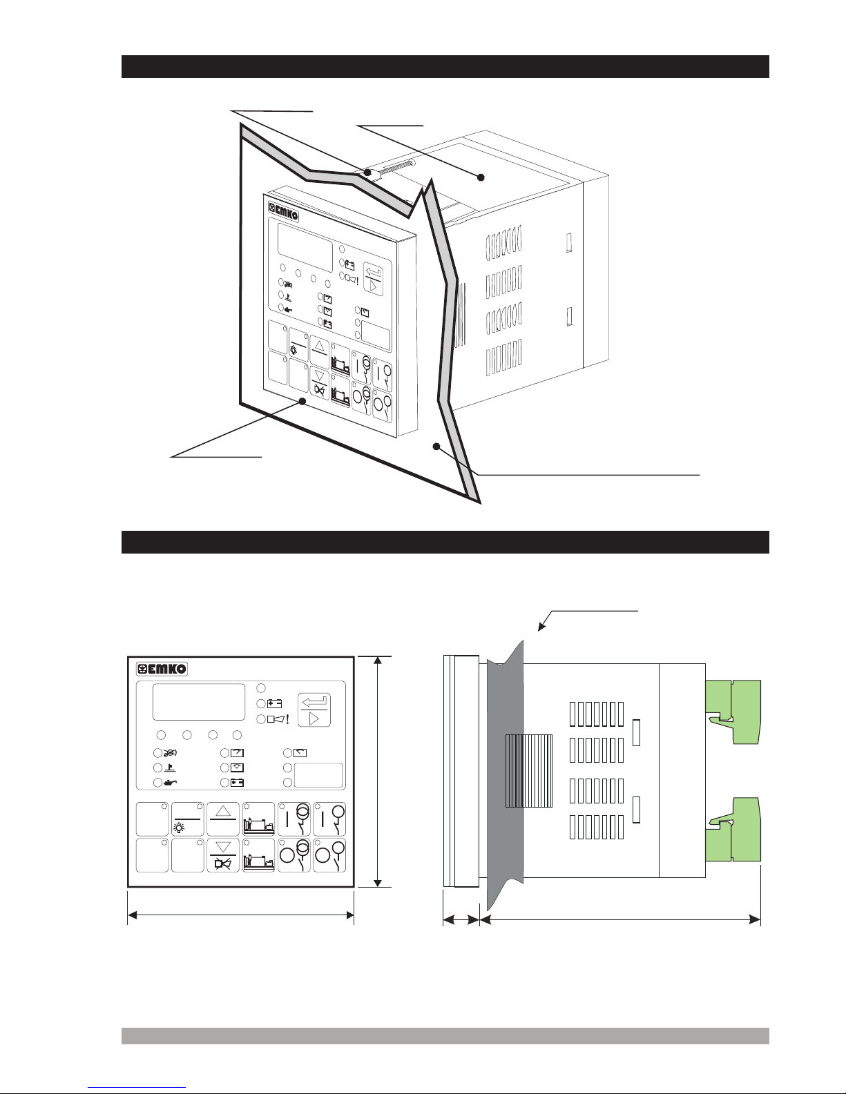
2.3 PANEL CUT-OUT.......................................................................................................................
2.4 ENVIRONMENTAL RATINGS....................................................................................................
2.5 PANEL MOUNTING...................................................................................................................
2.6 INSTALLATION FIXING CLAMP................................................................................................
2.7 REMOVING FROM THE PANEL...............................................................................................
3.1 TERMINAL LAYOUT AND CONNECTION INSTRUCTIONS....................................................
3.4 UNIT WIRING............................................................................................................................
1.2 WARRANTY...............................................................................................................................
1.3 MAINTENANCE.........................................................................................................................
2.2 DIMENSIONS............................................................................................................................
3.2 ELEKTRICAL CONNECTION DIAGRAM..................................................................................
3.2.1 EAOM-19 SINGLE PHASE CONNECTIONS SCHEMATIC FOR TN-C AC POWER
SYSTEMS........................................................................................................................
3.2.2 EAOM-19 THREE PHASE CONNECTIONS SCHEMATIC FOR TN-C AC POWER
SYSTEMS........................................................................................................................
3.3 TOP LABEL VIEW OF THE EAOM-19......................................................................................
3.5 UNIT WIRING DESCRIPTION..................................................................................................
4.1 FRONT PANEL DESCRIPTION................................................................................................
4.2 ACCESSING TO THE OPERATOR PARAMETERS.................................................................
4.3 ACCESSING TO THE TECHNICIAN PARAMETERS...............................................................
4.4 PARAMETER LIST....................................................................................................................
4.5 EXPLANATION OF PARAMETERS..........................................................................................
4.5.1 MAINS VOLTAGE CONNECTION (P00) AND DISCONNECTION LEVEL (P01),
UPPER LIMIT (P02).........................................................................................................
4.5.2 ALTERNATOR VOLTAGE LOWER (P03) AND UPPER LIMIT (P04), FAULT CONTROL
DELAY (P20)....................................................................................................................
4.5.3 ALTERNATOR FREQUENCY LOWER LIMIT (P51) AND UPPER LIMIT (P52), FAULT
CONTROL DELAY (P21).................................................................................................
4.5.4 ENGINE COOLING TIME (P07).......................................................................................
4.5.5 MAINS TRANSITION DELAY (P09).................................................................................
4.5.6 BATTERY VOLTAGE LOWER LIMIT (P11)......................................................................
4.5.7 STOP / FUEL SOLENOID SELECTION (P13).................................................................
4.5.8 STOP MAGNET ENERGISED TIME (P14)......................................................................
4.5.9 ENGINE STARTED SIGNAL (P15)................................................................................
4.5.10 STARTING ATTEMPT DURATION(P16), NUMBER OF STARTING ATTEMPTS(P06)..
4.5.11 CONTROL ON DELAY (P19)..........................................................................................
4.5.12 CONFIGURABLE INPUTS 1 AND 2 (P22 AND P23).....................................................
4.5.13 HORN OUTPUT SELECTION (P24)..............................................................................
4.5.14 CHOKE TIME (P25).......................................................................................................
4.5.15 GENERATOR START DELAY (P26)..............................................................................
4.5.16 OIL SENSOR SELECTION (P27)..................................................................................
4.5.17 ENGINE WORKING TIME (P28).....................................................................................
4.5.18 OPERATOR PASSWORD (PoPS)..................................................................................
4.5.19 TECHNICIAN PASSWORD (PtPS).................................................................................
5.1 MANUAL MODE........................................................................................................................
5.2 AUTO MODE.............................................................................................................................
5.3 TEST MODE..............................................................................................................................
4.DEFINITION OF FRONT PANEL AND ACCESSING TO THE PARAMETERS................................
5.COMMISSIONING..............................................................................................................................
CONTENTS
3
Page 6
Page 19
Page 13
Page 8
Page 9
Page 6
Page 7
Page 7
Page 9
Page 10
Page 11
Page 11
Page 12
Page 12
Page 13
Page 14
Page 14
Page 15
Page 16
Page 17
Page 18
Page 19
Page 21
Page 23
Page 25
Page 26
Page 26
Page 27
Page 27
Page 27
Page 27
Page 27
Page 28
Page 28
Page 28
Page 29
Page 29
Page 29
Page 29
Page 31
Page 31
Page 32
Page 32
Page 30
Page 30
Page 30
Page 30
Page 27

6.OPERATION.......................................................................................................................................
7.FAULT FINDING.................................................................................................................................
8.SPECIFICATIONS..............................................................................................................................
9.BLOK DIAGRAM................................................................................................................................
10. USER DEFINED PARAMETERS.....................................................................................................
6.1 ALTERNATE DISPLAY DESCRIPTION.....................................................................................
6.2 FAILURE INDICATORS DESCRIPTION...................................................................................
6.3 MODE TRANSITION.................................................................................................................
6.4 MANUAL START........................................................................................................................
6.5 MANUAL STOP..........................................................................................................................
6.6 AUTO OPERATION...................................................................................................................
6.7 TEST OPERATION....................................................................................................................
LIST-1...............................................................................................................................................
4
Page 40
Page 43
Page 39
Page 42
Page 43
Sayfa 33
Sayfa 33
Sayfa 36
Sayfa 38
Sayfa 38
Sayfa 38
Sayfa 38
Sayfa 38

Manufacturer’s Name : EMKO ELEKTRONIK A.S.
Manufacturer’s Address : DOSAB, Karanfil Sk., No:6,
16369 Bursa, TURKEY
Product Name : Automatic Transfer Unit For Diesel Generators
Type Number : EAOM-19
Product Category : Electrical equipment for measurement, control and
laboratory use
This declaration is issued under the sole responsibility of the manufacturer.
The product(s) that are stated above are fully in conformity with the essential requirements of
Council Directives:
This declaration is based on the full compliance of the products with the following European
standards:
2014 / 35 / EU The Low Voltage Directive
2014 / 30 / EU The Electromagnetic Compatibility Directive
EN 61000-6-4:2007 EMC Generic Emission Standard for Industrial Environments
EN 61000-6-2:2005 EMC Generic Immunity Standard for Industrial Environments
EN 61010-1:2010 Safety Requirements for electrical equipment for measurement, control
and laboratory use
EN 60947-6-1:2005/A1:2014 Low - voltage switchgear and controlgear - Part 6-1: Multiple
function equipment - Transfer switching equipment
02 March 2017 Name : Serpil YAKIN
BURSA-TURKEY Position : Quality Manager
When and Where Issued Authorized Signature
nd
5
EU DECLARATION OF CONFORMITY

1.Introduction
6
The EAOM-19 provides for automatic transfer of a load from mains to generator in the event of a
mains failure. The unit is able to detect failure of any phase of the mains and to start and switch
over to a generator if the mains voltage goes outside pre-set limits. Both automatic and manual
control is possible. A test mode is also available which allows the generator to be run without
taking the load. The unit monitors generator operation and gives warning of any faults that are
detected. It monitors:
Mains voltage
Engine speed
Battery voltage
Engine temperature
Oil pressure
It controls:
Engine fuel supply or engine stopping, (via external solenoid)
Starter motor, (via external relay)
Automatic generator start and load transfer on mains failure, (via external mains and
generator contactors)
Alarm horn
A four-digit, seven-segment display provides extensive monitoring of unit and generator
parameters, including:
Mains voltages
Alternator voltage and frequency
Battery voltage
Error indication
Program parameters
The unit is extensively programmable, with password protection on two levels. In the event that
the engine fails to start on the first attempt, the attempt will be repeated a programmed number of
times or until successful. If a fault is detected, the unit shuts down the engine and indicates the
failure by flashing a relevant fault LED. Two user configurable inputs are included that sound an
external horn, flash indicators on the panel and can be programmed to stop the engine,
disconnect the load or the remote inhibit.
Ÿ
Ÿ
Ÿ
Ÿ
Ÿ
Ÿ
Ÿ
Ÿ
Ÿ
Ÿ
Ÿ
Ÿ
Ÿ
Ÿ
Ÿ
Alternator output (voltage and frequency)
Engine working timeŸ
1.1 General Specifications

7
1.2 Warranty
EMKO Elektronik warrants that the equipment delivered is free from defects in material and
workmanship. This warranty is provided for a period of two years. The warranty period starts from
the delivery date. This warranty is in force if duty and responsibilities which are determined in
warranty document and instruction manual performs by the customer completely.
1.3 Maintenance
If the device is used with conditions which are explained in this instruction manual, there is no
need to do periodic maintenance.

8
In package,
- One piece unit
- Two pieces fixing clamp
- One piece instruction manual
A visual inspection of this product for possible damage occured during shipment is
recommended before installation. It is your responsibility to ensure that qualified
mechanical and electrical technicians install this product.
If there is danger of serious accident resulting from a failure or defect in this unit , power
off the system and seperate the electrical connection of the device from the system.
The unit is normally supplied without a power switch or a fuse. Use power switch and fuse
as required.
Be sure to use the rated power supply voltage to protect the unit against damage and to
prevent failure.
Keep the power off until all of the wiring is completed so that electric shock and trouble
with the unit can be prevented.
Never attempt to disassemble, modify or repair this unit. Tampering with the unit may
results in malfunction, electric shock or fire.
Do not use the unit in combustible or explosive gaseous atmospheres.
During the equipment is putted in hole on the metal panel while mechanical installation
some metal burrs can cause injury on hands, you must be careful.
Montage of the product on a system must be done with it’s fixing clamps. Do not do the
montage of the device with in appropriate fixing clamp. Be sure that device will not fall
while doing the montage.
Before beginning installation of this product, please read the instruction
manual and warnings below carefully.
2.Installation
c

9
2.1 General Description
2.2 Dimensions
Maximum 15 0.590 inchmm /
72mm / 2.834 inch
72mm / 2.834 inch
83.5 mm / 3.287 inch
11.5mm / 0.452 inch
Product Label
Front Panel
IP65 protection
NEMA 4X
Panel Surface
(maximum thickness 15mm / 0.590 inch)
Fixing Clamp
UV
Hz.
OFF AUTO
TEST
VL31/L3N
VL23/L2N
VL12/L1N
PROG
TEST RESET
G
G
EAOM - 19
MAN.
START
MAN.
STOP
~~
~
~
~
~
RPM
VV
FAILED
TO START
HIGH
TEMPERATURE
LOW OIL
PRESSURE
OVER SPEED
FAILURE
VOLTAGE
FAILURE
CHARGING
FAIL
VZ
BATT. VOLT.
FAILURE
UV
Hz.
OFF AUTO
TEST
VL31/L3N
VL23/L2N
VL12/L1N
PROG
TEST RESET
G
G
EAOM - 19
MAN.
START
MAN.
STOP
~ ~
~~~~
RPM
VV
FAILED
TO START
HIGH
TEMPERATURE
LOW OIL
PRESSURE
OVER SPEED
FAILURE
VOLTAGE
FAILURE
CHARGING
FAIL
VZ
BATT. VOLT.
FAILURE

10
2.3 Panel Cut-Out
97 mm / 3.82 inch (min)
69mm / 2.72 inch
69mm / 2.72 inch
Table des matières
Autres manuels EMKO Unité de contrôle
Manuels Unité de contrôle populaires d'autres marques

Festo
Festo Compact Performance CP-FB6-E Manuel de la liste des pièces

Elo TouchSystems
Elo TouchSystems DMS-SA19P-EXTME Manuel utilisateur

JS Automation
JS Automation MPC3034A Manuel utilisateur

JAUDT
JAUDT SW GII 6406 Series Guide rapide

Spektrum
Spektrum Air Module System Manuel utilisateur

BOC Edwards
BOC Edwards Q Series Manuel utilisateur


