Viale Caduti per la Libertà, 4/B - 40050 MONTE S. PIETRO - BOLOGNA (ITALY)
NOTA 2
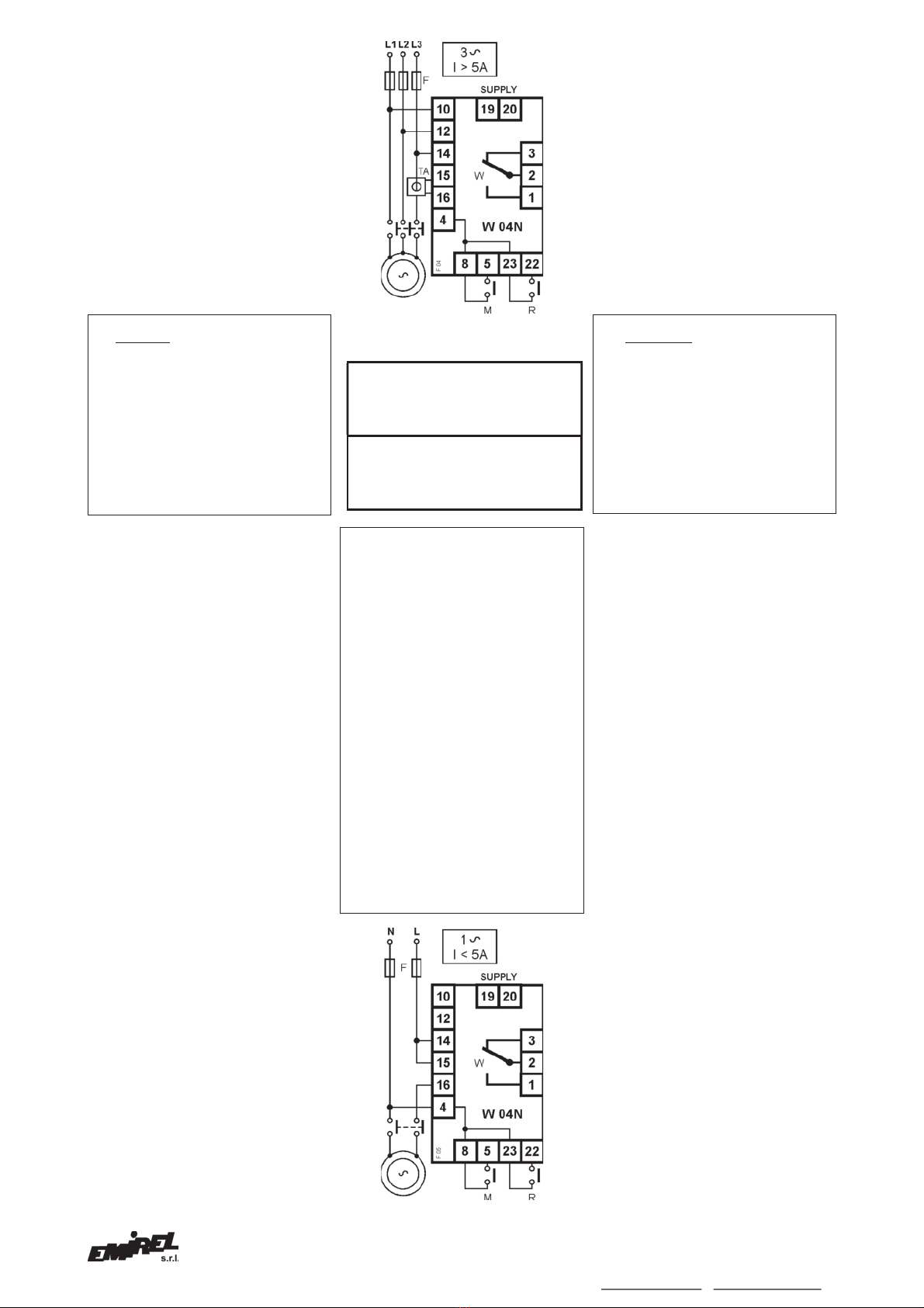
La fase di cui viene misurata la corrente
(fase AMPEROMETRICA) deve essere
collegata al pin 14. Il collegamento delle
altre due fasi non deve rispettare alcun
vincolo. Per l’eventuale inversione della
rotazione del motore, non utilizzare la
fase amperometrica.
Per applicare un W 04N occorre
determinare i seguenti due elementi:
1.) tensione del carico (400 Vac ecc.)
2.) I = corrente presente in linea
quando la potenza è massima.
Esempi per illustrare il criterio e le
modalità di definizione del fondo scala.
a) Se I é minore di 5A si può usare l’in-
serzione diretta (v. schemi di fig.3 e 5).
b) Se I é maggiore di 5A si deve usare
un riduttore di corrente (TA)…/5
oppure .../1 (schema di fig.4 e 5b).
ESEMPIO A)
Tensione carico 400Vac, I=5A (fig.3).
Nella colonna DIRETTA di TAB A, è
indicato il fondo scala pratico: 2 kW-
corrispondente al fondo scala della
corrente (5A in questo caso), ai quali
corrispondono 125 W di potenza
inversa.
ESEMPIO B)
Tensione carico 400 Vac, I = 20A.
Il collegamento si esegue secondo
fig.4.
Dalla tabella A si ricava che il fondo
scala di corrente più vicino,
immediatamente superiore al valore di
I, è 25A.
In questo caso il fondo scala deve
essere realizzato con un TA esterno.
Se il TA è ../5 si userà il modello 2.
Se il TA è ../1 si userà il modello 1.
Sia con TA 50/5 o 50/1, il filo della fase
amperometrica passa due volte
all’interno del TA (fig.2) e si collega al
pin. 14. Il secondario del TA si collega
ai pin 15 e 16.
INGRESSO
Pin voltmetrici: 10,12,14.
Ring = 800 kΩ
Si veda NOTA 2.
Pin amperometrici: 15, 16.
Nessuna sequenza da rispettare.
La massima tensione trifase è 415Vac.
Per tensioni maggiori si può utilizzare:
M 08: Resistenze di caduta + TA per
garantire l’isolamento.
USCITA
5A(NA) 3A(NC)-230 Vac carico
resistivo
W2-1 NA Dispositivo non
2-3 NC alimentato o in allarme
ALIMENTAZIONE: monotensione
2,5VA 50-60Hz tolleranza ±10%
19-
20: 115Vac o 230Vac o 24Vac o
48Vac
DIMENSIONI
105x90x75 mm – “modulare” per guida
DIN per finestratura. Accessorio a
richiesta: M48E protezione trasparente
piombabile.
TEMP. DI FUNZIONAMENTO: 0÷70°C
PESO: Kg 0,550 COLORE: grigio
Fig. 5b
NOTA 3
La grandezza del TA va scelta in
funzione della CORRENTE presente in
linea quando la potenza DIRETTA é
massima.
REMARK 3
The size of the CT is chosen basing on
the current correspondent to the
maximum DIRECT power.
NOTA 4
Per un miglior utilizzo del relè
wattmetrico, si consiglia di scegliere un
fondo scala di poco superiore al valore di
I.
REMARK 4
For the best working of W 04N, the
current full scale must be slightly greater
than ( I ) motor current.
NOTA 5
Si consiglia vivamente l’uso di gruppi RC
sulle bobine dei teleruttori.
REMARK 5
The application of RC groups on the
contactors coils is highly recommended.
Nota generale: Negli schemi di
collegamento non sono riportati i fusibili
sulle alimentazioni e sugli ingressi
voltmetrici. I collegamenti elettrici devono
essere eseguiti a dispositivo e quadro
elettrico spenti.
General remark: The wiring diagrams
do not show the fuses installed on the
supply and on the voltmetric inputs.
The electric wirings must be realized with
device and electrical panel in off
Per la pulizia usare un panno imbevuto di
detergenti privi di: Alcool denaturato,
Benzene, Alcool isopropilico.
For cleaning use a cloth soaked with
detergents without: Denatured Alcohol,
Benzene, Isopropyl Alcohol.
NOTA: Il TA esterno dovrebbe
avere una PRESTAZIONE ³5VA
per rispettare il FATTORE DI
POTENZA.
REMARK: The external CT must
have the BURDEN
³
5VA to not
REMARK 2
The phase in which the current is
measured (AMPEROMETRIC phase)
must be connected to pin 14. For the
connection of the other two phases no
constraints must be respected. For the
possible inversion of the motor rotation,
the amperometric phase must not be
For the application of W 04N the follo-
wing elements are necessary:
1.) Load voltage (400 Vac etc.)
2.) I = current present on the line
when the power is at the
maximum.
Examples for the full scale selection:
a) If Ip is lower than 5A the device is by
direct insertion connected (fig. 3 and 5)
b) If I is higher than 5A it is requested a
current transformer (CT) .../5 or .../1
(fig.4 and 5b).
EXAMPLE A)
Load voltage 400Vac, I=5A (fig.3).
In the column DIRECT of TAB A it is
showed the practical full scale: 2 kW
equivalent to the full scale of the
current (5A in this case),correspondent
to 125 W of reverse power.
EXAMPLE B)
Load voltage 400 Vac - It = 20A
The connection is made according to
fig.4.
The table A shows that the suitable
range is 25A slightly higher than the (I)
current. In this case is necessary the
application of an extern current
transformer (CT).
If the CT is ../5, the model 2 is applied.
If the CT is.../1, the model 1 is applied.
Both with CT .../5A and .../1A the
current wire is passed twice through
the CT (fig.2) and connected to the pin
14. Connect the secondary of the CT to
the pins 15 - 16.
INPUT
Voltage pins : 10, 12, 14.
Input Resistance = 800 kΩ
See REMARK 2.
Current pins : 15, 16.
No specific order to be followed.
The maximum threephase voltage is
415 Vac. For higher voltages, it is
requested the application of:
M 08 : Threephase drop resistances +
CT for insulation.
OUTPUT RELAY
5A(NO) 3A(NC)-230 Vac resistive load
W2-1 NO Device not supplied
2-3 NC or in alarm
SUPPLY: single voltage
2,5VA 50-60 Hz tolerance ±10%
19-20: 115Vac or 230Vac or 24Vac or
48Vac
DIMENSIONS
105x90x75 mm – “modular” for rail DIN
flush mounting. Accessory on request:
M48E transparent cover fitted for tight
closure.
WORKING TEMPERATURE: 0÷70°C
WEIGHT: Kg 0,550 COLOUR: grey