ElevATE Semiconductor Vesuvius Manuel utilisateur

Vesuvius EVM Getting Started Rev A2: 06/26/17
Copyright Elevate Semiconductor Corporation 2016 Page 1 of 30
Vesuvius EVM Getting Started
Rev A2: 06/26/17
This document contains information on a product under development and the material is
subject to change.

Vesuvius EVM Getting Started Rev A2: 06/26/17
Copyright Elevate Semiconductor Corporation 2016 Page 2 of 30
Table of Contents
1Introduction ..........................................................................................................................................................4
1.1Unpacking - Vesuvius EVM Contents ........................................................................................................ 4
1.2Recommended Test and Measurement Setup ........................................................................................... 5
1.2.1Power Supply ......................................................................................................................................... 5
1.2.2PC Controller ......................................................................................................................................... 5
1.2.3DMM or Source Measurement Unit ...................................................................................................... 5
1.3Software Installation ................................................................................................................................... 6
1.3.1Vesuvius EVM UIP Installation ............................................................................................................ 6
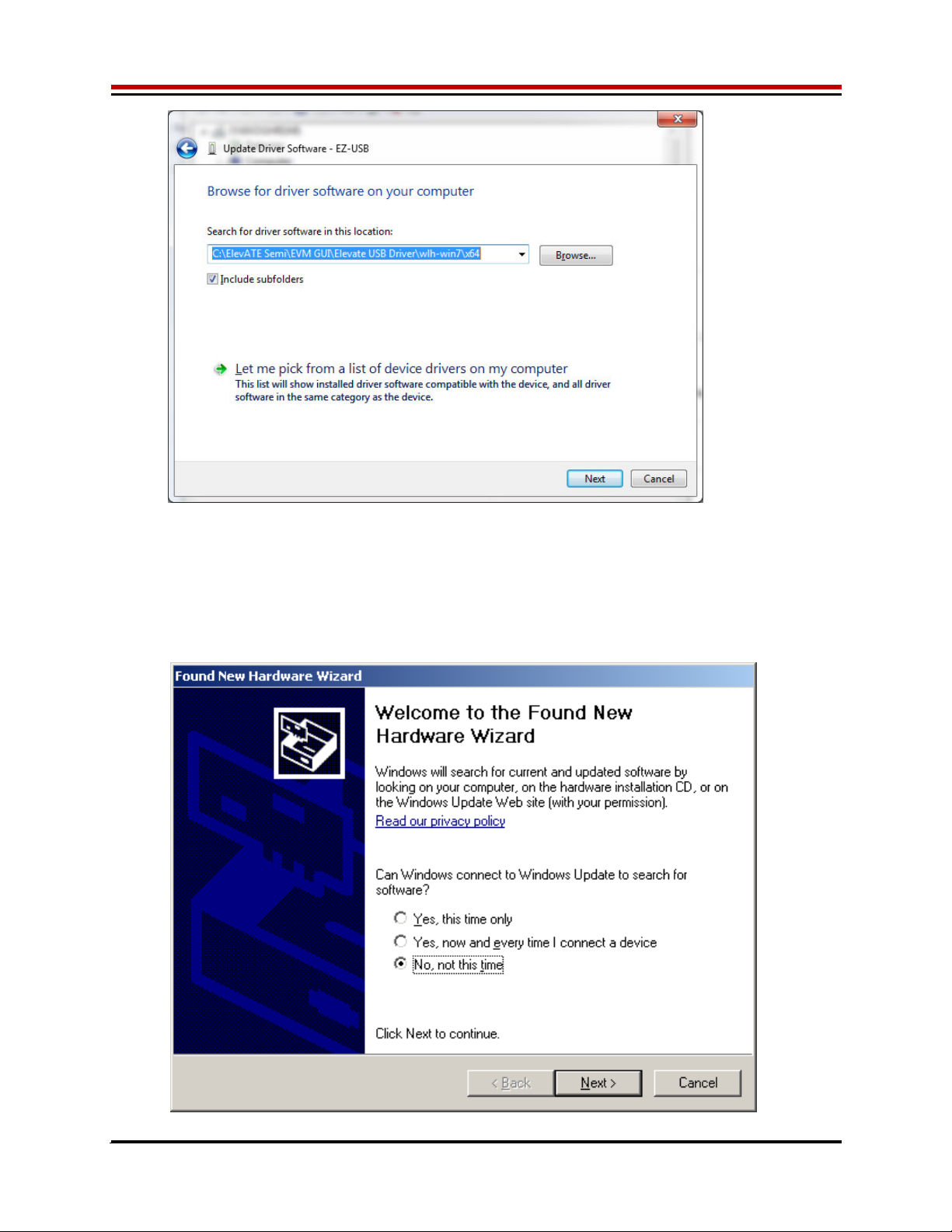
1.3.2USB Device Driver Installation ............................................................................................................. 6
1.3.3Reboot Machine ................................................................................................................................... 12
1.3.4Launching the Elevate Semiconductor Program .................................................................................. 1 2
1.3.5Software Un-Installation ...................................................................................................................... 12
2Getting Started ....................................................................................................................................................13
2.1Caution ....................................................................................................................................................... 13
2.2Quick Start Instructions ............................................................................................................................ 13
2.2.1Default Power Supply Option .............................................................................................................. 13
2.3Default Configuration Setup Options ...................................................................................................... 15
2.3.1Remote Kelvin Sense ........................................................................................................................... 15
2.3.2FV/MI Configuration ........................................................................................................................... 16
2.3.3FI/MV Configuration ........................................................................................................................... 17
2.3.4Channel#0 and Channel#1 Ganging (Merging) Configuration ............................................................ 18
2.3.5All channels in Ganged (Merging) Configuration ............................................................................... 1 9
2.4Motherboard Jumper and SMA Definition ............................................................................................. 20
2.5Vesuvius Loadboard Jumper Definitions ................................................................................................ 21
2.6Vesuvius EVM Menu and Dialog Boxes .................................................................................................. 22
3Vesuvius EVM Loadboard Detailed Description ...............................................................................................27
3.1Vesuvius EVM Loadboard Controller ..................................................................................................... 29
4Document Revision History................................................................................................................................30

Vesuvius EVM Getting Started Rev A2: 06/26/17
Copyright Elevate Semiconductor Corporation 2016 Page 3 of 30
List of Figures
Figure 1: Installation Directory Structure ...................................................................................................... 6
Figure 2: Expected Current Readings ........................................................................................................ 14
Figure 3: Vesuvius EVM FV/MI Simplified Block Diagram ......................................................................... 16
Figure 4: Vesuvius EVM FI/MV Simplified Block Diagram ......................................................................... 17
Figure 5: Vesuvius EVM Ganging Configuration Simplified Block Diagram .............................................. 18
Figure 6: Vesuvius EVM All Channels Ganging Configuration Simplified Block Diagram ......................... 19
Figure 7: Device Configuration Menu Options ............................................................................................ 22
Figure 8: Vesuvius Configuration Dialog Box ............................................................................................ 23
Figure 9: Vesuvius DC Levels Dialog Box ................................................................................................. 24
Figure 10: Vesuvius DAC Configuration Dialog Box .................................................................................. 25
Figure 11: Vesuvius Central Register Dialog Box ...................................................................................... 26
Figure 12: Vesuvius EVM Detailed Block Diagram .................................................................................... 27
Figure 13: Vesuvius Slave Detailed Block Diagram .................................................................................. 28
Figure 14: Controller Section Detailed Block Diagram .............................................................................. 29
List of Tables
Table 1: Vesuvius EVM Contents ................................................................................................................. 4
Table 2: Power Supply Requirements ......................................................................................................... 5
Table 3: Vesuvius Default Configuration Options ...................................................................................... 15
Table 4: Motherboard SMA and Jumper Definitions (Vesuvius Input Signals) .......................................... 20
Table 5: Motherboard SMA Definitions (Vesuvius Output Signals) ........................................................... 20
Table 6: Vesuvius Loadboard Jumper Definitions ..................................................................................... 21

Vesuvius EVM Getting Started Rev A2: 06/26/17
Copyright Elevate Semiconductor Corporation 2016 Page 4 of 30
1 Introduction
Congratulations on your purchase of an Elevate Semiconductor Vesuvius evaluation system. You will find
that it serves as an invaluable development platform to help get your product to market in the shortest
possible time. The Vesuvius and Graphical User Interface (GUI) allow the customer to demonstrate and
evaluate the Vesuvius performance and functionality.
This document provides the instructions to install, setup, and operate the Vesuvius EVM. Refer to the
Elevate Semiconductor EVM User’s Guide for a detailed description of the EVM system.
1.1 Unpacking - Vesuvius EVM Contents
Please check the contents of the Vesuvius EVM shipping carton to make sure you have received all of
the items listed in Table 1. The system is already configured for the best setup, except for connections to
the power supply, PC controller, and test equipment.
Table 1: Vesuvius EVM Contents
Qt
y
Description
1 ea. Vesuvius EVM System (3 boards: Motherboard, FVMI Board, Vesuvius
Loadboard
)
1 ea. Vesuvius EVM Gettin
g
Started
(
this document
)
1 ea. EVM Contents Lis
t
1 ea. Elevate Semiconductor User Interface Pro
g
ram Installation Flash Drive
1 ea. USB A/B Cable

Vesuvius EVM Getting Started Rev A2: 06/26/17
Copyright Elevate Semiconductor Corporation 2016 Page 5 of 30
1.2 Recommended Test and Measurement Setup
1.2.1 Power Supply
Table 2 provides the required power supplies and current rating. The power supplies are connected
using standard banana plugs. The customer needs to provide the power supply cables and supplies.
It is recommended to use a triple supply to control the EVM supplies. This allows the 3 EVM supplies to
be turned on at the same time. However, if this is not feasible, then the supplies should be enabled in the
following sequence. Power down should be performed in the reverse order.
1. +20V
2. -15V
3. +5V
The Vesuvius VCCO and VEE are gated using an Opto-FET switch on the loadboard so it is safe to set
and enable the Vesuvius supplies before powering up the EVM and running the software.
Table 2: Power Supply Requirements
Module Suppl
y
Current Ratin
g
Motherboard +20V 0.5
A
Motherboard +5V (1) 0.5
A
Motherboard -15V 0.5
A
Vesuvius VCCO +5V (2, 3) 5.0
A
(4)
Vesuvius VEE -3V (2, 3) 5.0
A
(4)
Notes:
1) The EVM +5V could also be used as the Vesuvius VCCO
2) Once the EVM operation is verified, the customer can adjust the VCCO, VEE supplies
3) Make sure the external supplies do not violate the ABS max section on the datasheet.
4) The VCCO and VEE current 4A requirements are required if all 8 channels are operating at
maximum current load. If using a sub-set of channels then a smaller (i.e. 1 Amp) supply could be
adequate. The program does not have the ability to measure the VCCO and VEE currents
1.2.2 PC Controller
To use the Vesuvius EVM User Interface Program (UIP), a PC with the following configuration is required:
Windows 2007, Windows 2008, Windows 2010
USB Port (a USB cable is provided)
1.2.3 DMM or Source Measurement Unit
Voltage and/or Current Meter
Voltage and/or Current Source

Vesuvius EVM Getting Started Rev A2: 06/26/17
Copyright Elevate Semiconductor Corporation 2016 Page 6 of 30
1.3 Software Installation
There are 2 steps to install the Vesuvius EVM demonstration program.
1. Install the Vesuvius EVM UIP from the Flash Drive.
2. Install the USB driver.
Figure 1 illustrates the default directory structure. The user may change the <root dir> during the
installation.
Figure 1: Installation Directory Structure
<Root Dir>:\ElevATE Semi
1.3.1 Vesuvius EVM UIP Installation
To install the Vesuvius EVM software package, run the SETUP program on the distribution Flash Drive
and follow the prompts. The ElevATE.exe executable will be installed in the EVM GUI sub-directory. In
addition, a short cut will be installed onto the desktop and in the Start->Programs folder. The
Start->Programs folder also contains links to the different EVM User’s Guide, and documentation
folders.
1.3.2 USB Device Driver Installation
Follow section 1.3.2.1 for installation instructions on the Windows 10/8 operating systems, section 1.3.2.2
for instructions for Windows 7, or section 1.3.2.3 for Windows XP
1.3.2.1 Window 10/8
To install the USB driver on Windows 10/8, the Driver Signature Verification needs to be disabled.
This is accomplished using the following method.
1.3.2.1.1 Enter the Troubleshoot menu. Click “Restart” from the power options menu and hold
down the “Shift” key at the same time. Once the computer has rebooted, you will be
able to choose the Troubleshoot option.

Vesuvius EVM Getting Started Rev A2: 06/26/17
Copyright Elevate Semiconductor Corporation 2016 Page 7 of 30
1.3.2.1.2 Select “Advanced options” and “Startup Settings”.
1.3.2.1.3 You need to restart your computer one last time to modify boot time configuration
settings.
1.3.2.1.4 You will be given a list of startup settings, including “Disable driver signature
enforcement”. To choose the setting, you need to press the “F7” key. This will disable
the driver signature enforcement until the computer is rebooted.

Vesuvius EVM Getting Started Rev A2: 06/26/17
Copyright Elevate Semiconductor Corporation 2016 Page 8 of 30
1.3.2.1.5 Continue with section 1.3.2.2 to finish installation of USB driver except choose the
windows 10 or windows 8 option.
1.3.2.2 Windows 7
To install the USB device driver on a Windows 7 system, connect the USB port using the included
USB A/B cable. The USB port does not need any external power or need to be connected to any
other board for the device driver installation.
1.3.2.2.1 After connecting the USB cable from the PC to the “USB FX2 to Parallel” board,
navigate to the Device Manager screen on your computer and look for the EZ-USB
Icon. Right-Click on the EZ-USB Icon and select “Update Drive Software…”

Vesuvius EVM Getting Started Rev A2: 06/26/17
Copyright Elevate Semiconductor Corporation 2016 Page 9 of 30
1.3.2.2.2 Select “Browse my computer for driver software”.
1.3.2.2.3 Install driver from the newly installed folder on your computer:
Windows 7: \ElevATE Semi\EVM GUI\Elevate USB Driver\wlh-win7\(x64 or x86)
Select x64 for a 64-bit system.
Select x86 32-bit system.
Select “Next”. The USB driver will be installed.

Vesuvius EVM Getting Started Rev A2: 06/26/17
Copyright Elevate Semiconductor Corporation 2016 Page 10 of 30
1.3.2.3 Windows XP
To install the USB device driver on a Windows XP system, connect the USB port using the
included USB A/B cable. The USB port does not need any external power or need to be
connected to any other board for the device driver installation.
1.3.2.3.1 After connecting the USB cable from the PC to the USB port, the following window
appears. Select “No, not this time” and click Next.
Ce manuel convient aux modèles suivants
1
Table des matières
Autres manuels ElevATE Semiconductor Carte mère
Manuels Carte mère populaires d'autres marques

Telit Wireless Solutions
Telit Wireless Solutions SL869-3DR Manuel utilisateur

Gigabyte
Gigabyte GA-9IVDT Manuel utilisateur

Texas Instruments
Texas Instruments ADS8372EVM Manuel utilisateur

Commell
Commell MS-C73 Manuel utilisateur

IBT Technologies
IBT Technologies MB860 Manuel utilisateur

Nvidia
Nvidia TEGRA DG-04927-001_V01 Manuel utilisateur


