EKF C20-SATA Manuel

Technical Information
C20-SATA
SATA Dual-Drive
Mezzanine Module
Document No. 5421 • Ed. 3 • 22 January 2013

Technical Information C20-SATA • SATA Dual-Drive Mezzanine Module
Contents
AboutthisManual ........................................................... 3
EditionHistory......................................................... 3
RelatedDocuments ..................................................... 4
Nomenclature ......................................................... 4
TradeMarks .......................................................... 4
Legal Disclaimer - Liability Exclusion ......................................... 4
Standards ............................................................ 4
FeatureSummary............................................................ 5
ShortDescription....................................................... 6
BlockDiagram......................................................... 7
TopViewComponentAssembly ........................................... 8
Mounting Alternates .................................................... 9
InstallingandReplacingComponents............................................ 11
BeforeYouBegin...................................................... 11
Warnings ...................................................... 11
Caution ....................................................... 11
InstallingtheBoardAssembly ............................................ 12
RemovingtheBoardAssembly............................................ 13
EMCRecommendations................................................. 14
Technical Reference - Connectors ............................................... 15
Caution............................................................. 15
PleaseNote .......................................................... 15
I/O Connectors ....................................................... 16
J2/J3SATADockingHeader(s)....................................... 17
P1SATACableHeader ............................................ 19
P2ExternalPower................................................ 20
Inter-Board Connector .................................................. 21
Schematics................................................................ 23
© EKF -2- ekf.com

Technical Information C20-SATA • SATA Dual-Drive Mezzanine Module
About this Manual
This manual is a short form description of the technical aspects of the C20-SATA, required for
installation and system integration. It is intended for the advanced user only.
Edition History
EKF
Document
Ed. Contents/Changes Author Date
Text # 5421
c20_tie.wpd
1 Technical Information C20-SATA
English, Preliminary Edition
jj 24 February
2009
2 Added more photos jj 16 November
2009
3 Added photo PC1-PCS-C20 jj 22 January 2013
© EKF -3- ekf.com

Technical Information C20-SATA • SATA Dual-Drive Mezzanine Module
Related Documents
The C20-SATA is a passive module, intended for use on a suitable active carrier card. For a description
of the related carrier board, please consult the associated technical document(s), e.g.
CCI-RAP: www.ekf.com/c/ccpu/cci/ccie_tie.pdf
CCK-MARIMBA: www.ekf.com/c/ccpu/cck/cck_tie.pdf
CCL-CAPELLA: www.ekf.com/c/ccpu/ccl/ccl_tie.pdf
CCO-CONCERT: www.ekf.com/c/ccpu/cco/cco_tie.pdf
CE4-PIANO: www.ekf.com/c/cide/ce4/ce4_tie.pdf
PCS-BALLET: www.ekf.com/p/pcs/pcs.html
Change path accordingly for other possible carrier boards.
Nomenclature
Signal names used herein with an attached '#' designate active low lines.
Trade Marks
Some terms used herein are property of their respective owners, e.g.
<Intel, Pentium, Celeron, Core: ® Intel
<CompactPCI ®: ® PICMG
<Windows XP, WEPOS, POSReady, Windows 7: ® Microsoft
<EKF, ekf system: ® EKF
EKF does not claim this list to be complete.
Legal Disclaimer - Liability Exclusion
This document has been edited as carefully as possible. We apologize for any potential mistake.
Information provided herein is designated exclusively to the proficient user (system integrator,
engineer). EKF can accept no responsibility for any damage caused by the use of this manual.
Standards
Specifications/Standards
SATA Serial ATA 2.5/2.6 Specification (www.sata-io.org)
© EKF -4- ekf.com

Technical Information C20-SATA • SATA Dual-Drive Mezzanine Module
Feature Summary
Feature Summary
Form Factor Proprietary size mezzanine module, basically fits into the 4HP (20.32mm) envelope of the
carrier board, typically delivered as a ready to use assembly unit comprising of carrier board,
CPU base board, drive(s), mounting position right (on top of carrier board)
Host I/F Connector
(Bottom Mount, to
Carrier)
<J1 High speed female mezzanine connector, corresponds to carrier board male
connector
<Two independent SATA channels, RAID or non-RAID configurable
<Nominal headroom 6mm between carrier board and C20-SATA (suitable for single
top-mount drive), resulting from 4mm height J1 + 2mm height carrier board
connector
SATA Usage <J2: Horizontal mount docking connector, suitable for top mount 2.5-inch SATA
SSD/HDD
<Option J3: Horizontal mount docking connector, suitable for bottom mount 2.5-
inch SATA SSD/HDD
<Option P1: Vertical SATA connector suitable for latching SATA cable assembly
<Options J3 and P1 provided exclusive to each other
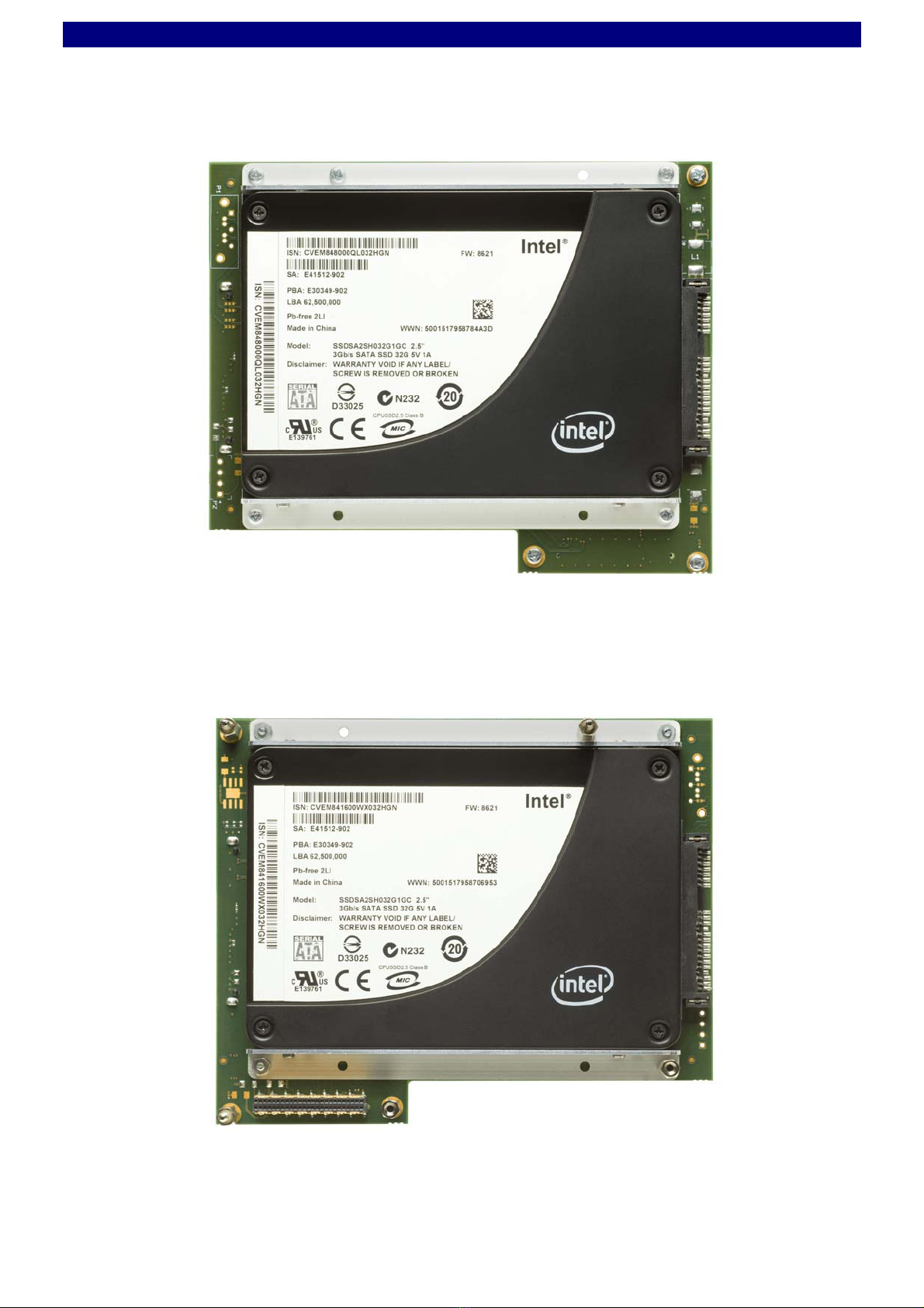
On-Board Storage <2.5-Inch SATA on-board drive option
<Single drive (top mount) for low profile
<Dual drive (top & bottom mount) option
<Solid State Drive (SSD) or Hard Disk Drive (HDD)
<Intel X-25E Single Level Cell (SLC) SSD recommended for ultra high speed
<Intel X-25M Multi Level Cell (MLC) SSD recommended for more storage capacity
<Hard disk recommended for low cost applications and maximum storage capacity
Thermal 1
Conditions
Environmental 1
Conditions
<Operating temperature: 0°C ... +70°C
<Storage temperature: -40°C ... +85°C, max. gradient 5°C/min
<Humidity 5% ... 95% RH non condensing
<Altitude -300m ... +3000m
<Shock 15g 0.33ms, 6g 6ms
<Vibration 1g 5-2000Hz
EC Regulations <EN55022, EN55024, EN60950-1 (UL60950-1/IEC60950-1)
<2002/95/EC (RoHS)
MTBF tbd
1Observe degradation of temperature limits and other conditions when hard disk drive is in use
- consult manufacturers data sheet - SSD recommended for rugged environment
Not all of the connectors may be present or functional on your actual C20-SATA board; assembly is
highly custom specific. Options may be exclusive, i.e. not necessarily concurrently present. Discuss
your needs with EKF before ordering.
© EKF -5- ekf.com

Technical Information C20-SATA • SATA Dual-Drive Mezzanine Module
Short Description
Available as a mezzanine add-on storage
module to several CPCI side boards, the
purpose of the C20-SATA is to accommodate
one or two 2.5-inch SATA drive(s), either SSD
(Solid State Drive) or HDD (Hard Disk Drive).
With respect to the dual drive solution, either
RAID or non-RAID drivers are available. Since
only a few components are required on the
C20-SATA PCB, it is a moderate cost system
storage solution.
The C20-SATA mounts on top of the carrier
board. Provided with a single (top mount) drive,
the 4HP profile of the associated carrier board
would be maintained, resulting in a 8HP total
assembly, comprised of the CompactPCI®base
board, the expansion carrier card (aka side
board), and the C20-SATA storage module.
As an option, the C20-SATA can be populated
with another (bottom mount) drive, resulting in
a 10HP or 12HP assembly stack.
The two SATA channels are derived from a
carrier board SATA controller (JMB362 as of
current), for RAID 0/1/10 operation, or normal
usage.
Solid state drives (SSD aka Flash Drive) are
recommended for fast and rugged operation.
Single level cell (SLC) drives offer the highest
transfer speed and superior reliability. A hard
drive should be considered as an economic
solution, with decreased operating temperature
and performance compared to a SSD, but
maximum storage capacity as of current.
© EKF -6- ekf.com

Technical Information C20-SATA • SATA Dual-Drive Mezzanine Module
Block Diagram
SATA
Docking Header
Option
SATA
Docking Header
SATA1J2
J3 P1
Top Mount
2.5-Inch
SATA
SSD HDD
Solid State Drive
Hard Disk Drive
Bottom Mount
2.5-Inch
SATA
SSD HDD
Solid State Drive
Hard Disk Drive
High Speed
Mezzanine
Connector
J1
Simplified Block Diagram
C20-SATA
Option
SATA
Cable Header
SATA
+5V
+3.3V +12V
P2
Option
External
Power
Options
C20-SATA on Top of an Assembly Stack
© EKF -7- ekf.com

Technical Information C20-SATA • SATA Dual-Drive Mezzanine Module
Top/Bottom View Component Assembly
C20-SATA Top View
C20-SATA Bottom View
© EKF -8- ekf.com

Technical Information C20-SATA • SATA Dual-Drive Mezzanine Module
Mounting Alternates
The C20-SATA will be mounted with a headroom of either 6mm - 10mm - 14mm or 18mm above the
carrier board, depending on the number of drives engaged (one or two), the drive height (7.0mm
typically for solid state drives, 9.5mm assumed for hard disk drives), and components on the carrier
board e.g. PCIe Mini Card sockets.
The 6mm headroom assembly fits into the 4HP envelope of the carrier board, which results in a total
assembly height of 8HP including the CPU base board. This version is limited to a single drive.
The 10mm headroom version is suitable for a second drive, bottom mount (SSD 7mm). No
components >2.8mm height would be allowed on the carrier board below the C20-SATA. This
assembly exceeds the 4HP envelope of the carrier board slightly, if also on top is a SSD populated.
The 14mm headroom assembly exceeds the 4HP envelope definitely. With a bottom mount 9.5mm
hard drive, components on the carrier board situated below the C20-SATA must not be higher than
4.3mm (6.8mm with a 7.0mm SSD).
The nominal 18mm headroom version is suitable for a dual drive C20-SATA, while not imposing too
much restrictions on components on the carrier board. With the real 18.6mm stand-off bolts in use,
components on the carrier board may be as high as 8.9mm (9.5mm bottom mount HDD), or 11.4mm
(7.0mm bottom mount SSD). A common front panel of 12HP is recommended for the entire assembly
comprised of CPU base board, carrier side card, and the C20-SATA dual drive module. EKF offers also
custom specific front panel design.
The different assembly versions are achieved by choosing mezzanine connectors with a suitable
height, on both the C20-SATA and on the carrier board as well. Be sure to specify your individual
needs when ordering.
Custom Specific 12HP Front Panel
© EKF -9- ekf.com

Technical Information C20-SATA • SATA Dual-Drive Mezzanine Module
SSD/HDD Bottom Mount 7.0mm
C20-SATA Assembly
Sectional Drawing (South View)
C20-SATA
Side Board 4HP Pitch
Carrier Board PCB (Side Board) 6.0mm
18.72mm nominal
18.6mm hex nut
CPU Board PCB (Base Board)
4mm fem
2mm male
J1
J2
SSD/HDD Top Mount 7.0/9.5mm
C20-SATA
Side Board 4HP Pitch
Carrier Board PCB (Side Board)
10.0mm
18.72mm nominal
18.6mm hex nut
CPU Board PCB (Base Board)
8mm fem
2mm male
J1
J2
SSD/HDD Top Mount 7.0/9.5mm
J3
SSD/HDD Bottom Mount 7.0/9.5mm
C20-SATA
Side Board 4HP Pitch
Carrier Board PCB (Side Board)
14.0mm
18.72mm nominal
18.6mm hex nut
CPU Board PCB (Base Board)
10mm male
J2
SSD/HDD Top Mount 7.0/9.5mm
J3
4mm fem
J1
© EKF • ekf.com
SSD/HDD Bottom Mount 7.0/9.5mm
C20-SATA
Side Board 4HP Pitch
Carrier Board PCB (Side Board)
18.72/
18.6mm
18.72mm nominal
18.6mm hex nut
CPU Board PCB (Base Board)
10mm male
J2
SSD/HDD Top Mount 7.0/9.5mm
J3
8mm fem
J1
© EKF -10- ekf.com
Table des matières
Manuels Unité de contrôle populaires d'autres marques

Festo
Festo Compact Performance CP-FB6-E Manuel de la liste des pièces

Elo TouchSystems
Elo TouchSystems DMS-SA19P-EXTME Manuel utilisateur

JS Automation
JS Automation MPC3034A Manuel utilisateur

JAUDT
JAUDT SW GII 6406 Series Guide rapide

Spektrum
Spektrum Air Module System Manuel utilisateur

BOC Edwards
BOC Edwards Q Series Manuel utilisateur


