Domburg KeerPlus3 Manuel utilisateur

Domburg Train Support
Your partner in model railroad technology
DTS
Manual
DTS Manual:
KeerPlus3
Reverse loop solution for DCC model railways
Version 2 - 2019

Manual KeerPlus3 │ version 2 – 2019
Page: 2 van 12
Content
Introduction .......................................................................................................................................................... 3
How the KeerPlus3 works ..................................................................................................................................... 4
The functionallity of the KeerPlus3 ................................................................................................................... 4
Requirements of the Reverse loop ................................................................................................................... 5
Mounting .............................................................................................................................................................. 5
View of the KeerPlus3 .......................................................................................................................................... 6
Connecting the KeerPlus3 .................................................................................................................................... 7
Power Supply .................................................................................................................................................... 7
DCC Signal ......................................................................................................................................................... 7
The Reverse loop .............................................................................................................................................. 8
Switching outputs ............................................................................................................................................. 9
Detection.........................................................................................................................................................10
FAQ .....................................................................................................................................................................11
I have everything connected, when the train enters the Reverse loop I get immediate closure. .................11
The train gives a short circuit if it enters section 3 from section 2. (Or from S2 to S1) .................................11
I do not receive a detection notification on the busy notification module ....................................................11
The module gives a detection on S1 while the locomotive runs in S3. ..........................................................11
Very occasionally I get a shotage when the loco enters one of the sections. ................................................11
Epilogue ..............................................................................................................................................................11

Manual KeerPlus3 │ version 2 – 2019
Page: 3 van 12
Introduction
Thank you for purchasing the KeerPlus3. This article has been specially developed for users who are
looking for a Reverse loop solution that is efficient and simple to use in addition to being cost effective.
With a digital model railway, a short circuit by applying a Reverse loop or by creating a differently
polarized part of the track is a common problem. These problems are easily solved by applying a Reverse
running solution that allows a part of the lane to change polarity. There are two types of circuits, the
short-circuit method and the current detection solution. The KeerPlus3 only uses the current detection
method. In this manual we explain how the solution works and how it can be applied to your model
railway.
I wish you a lot of ease of use with the KeerPlus3, if you have suggestions for improving the product or a
critical note. Let me know by sending an email to in[email protected]
Sincerely,
Martin Domburg
Domburg Train Support
Additional accessories that can be ordered separately:
- Mounting set circuit board
- Resistance 10 kΩ
- Meanwell power supply GS36E12
Disclaimer:
The KeerPlus3 was developed by Vincent Bogers for Domburg Train Support.

Manual KeerPlus3 │ version 2 – 2019
Page: 4 van 12
How the KeerPlus3 works
The functionality of the KeerPlus3
The KeerPlus3 works entirely based on current detection divided into three sections. Current detection
means that each section is detected along its entire length on power consumers such as locomotives or
carriages with lighting. In short, everything that consumes electricity.
As mentioned, the module uses three sections. As soon as the first section (S1) is activated by means of
detection, the module switches the second section (S2) and the last section (S3) into the same polarity as
S1. Subsequently section S2 is driven and as soon as the locomotive activates the last section S3, the
module immediately switches the S2 and the last section S3 to the opposite polarity. The first section S1
remains untouched so that it can be ridden again.
This works identically when the Reverse loop is driven from the other direction. In rest mode, the module
“sniffs” on sections S1 and S3 to a consumer. As soon as S1 is activated, the module converts S2 and S3
into the same polarity and switches the module at S3 together with S2. If S3 is switched first, the module
converts S1 and S2 to the same polarity and as soon as S1 is activated it converts S1 and S2 to the other
polarity. Because S3 then remains standing, a train can just enter it again.
.

Manual KeerPlus3 │ version 2 – 2019
Page: 5 van 12
Requirements of the Reverse loop
Because the module does not switch the first section, the rule applies that the section S2 must at least
have the length of the longest detected train. Should the train not fit in (for example a train set or a train
with a steering position), a short circuit will occur as soon as the wagons that are still in the first section
enter the reverse polarized S2.
Summary: S2 must be the length of the longest detected train.
In addition to the middle section S2, we also refer to S1 and S3, the two outer sections. The advice is to
use approximately 1.5x a locomotive length. In theory, a length of 5 centimetres would be enough to
generate a good detection. However, practice shows that contact between the rails and the wheels is
sometimes not guaranteed. To make the Reverse loop sections work reliably and stably, we recommend
using a longer length for this.
Mounting
The KeerPlus3 has 4 mounting points. It is advisable to mount the printed circuit board at height due to
the heat development of the voltage regulator. Preferably with the components on top.
Mounting the module in the upside down or lateral position is also possible if you consider the cooling of
the cooling element.
For the assembly you can use the printed circuit board assembly kit which
you can find in the webshop.

Manual KeerPlus3 │ version 2 – 2019
Page: 6 van 12
View of the KeerPlus3
1 Supply voltage (note: always connect)
2 DCC Signal from the control panel (note: always connect)
3/4 Section 3 (S3) A / B
5/6 Section 2 (S2) A / B
7/8 Section 1 (S1) A / B
9 Switch output Common
10/11/12 Switch outputs S1 / S2 / S3
13 Switch position S1
14 Switch position S2
15 Switch position S3
Aansluiten van de KeerPlus3

Manual KeerPlus3 │ version 2 – 2019
Page: 7 van 12
Connecting the KeerPlus3
Power Supply
The supply voltage that must be offered on the KeerPlus3 can be done in three different ways:
DC voltage 12-16 VDC
AC voltage 12-16 VAC
DCC Signal
The DCC signal means the Track Output of the control panel. The supply by a direct voltage supply is
preferred, however, because not everyone has it, it is also possible to use an AC transformer or the DCC
voltage. The module is not polarity sensitive, so it does not matter where you connect the plus and
minus.
DCC Signal
The figure shows the DCC input (2) to which you must connect the raw DCC voltage from your control
panel. In the base the left terminal is B and the right is terminal A. In the connection diagram we have
given the A a blue colour and the B a black colour.
Unfortunately, the output is not the same for every exchange, so you must experimentally discover which
order should be applied for you. Another variable is the way in which you have applied the polarity to
your lane.
If after connecting the Reverse loop you get a short circuit on your exchange as soon as a locomotive
enters the Reverse loop, that is an indication that you must switch the A and B connection on the
terminal 2 of your module.

Manual KeerPlus3 │ version 2 – 2019
Page: 8 van 12
The Reverse loop
In the image above you can see the three sections drawn with the corresponding connection to the
module. In this example you can see that the outer rail is A (blue) and the inner rail is B (black). This may
also be the other way around, if all three sections are on the same side A and on the same side B. At the
terminals you must also consistently maintain the A and B connection. If you change the A and B at the
terminals from 1 section, you will get a closure in that section.
It is also important that you do not swap the order of the sections, otherwise the module will switch
incorrectly.
Finally, it is important that all sections on both sides in the two rails are interrupted. You can do this by
using rail welding or cutting the rails. The sections are therefore not allowed to make contact in both A
and B. There are 3 LEDs on the module that show the polarization status per section. If the LED is off, the
polarization relay of that section is off, and if the LED is on, the polarization relay of that section is on and
the section reversed.
You must always connect both the DCC signal and the power
supply! So, make both connections, otherwise the KeerPlus3 will not
work.
You can also loop the DCC signal to the power input.
The KeerPlus3 does not get the power from the DCC input
because there are other ways to power the module.

Manual KeerPlus3 │ version 2 – 2019
Page: 9 van 12
Switching outputs
At the top there are 4 screw terminals (9 to 12) which switch based on current detection. As soon as
current detection is present in a section, a second relay will switch between these terminals. There are
three relays in total, one for each section.
Because the contacts are potential free, you can switch everything with it. Think of switches, LEDs,
signals, relays and so on. The operation is simple. You connect any voltage or signal, whichever suits you
best, to terminal 9. As soon as section 1 is detected, this voltage will be forwarded to terminal 10, upon
detection in S2 the voltage will be forwarded to terminal 11 and upon detection in S3 terminal 13
receives the voltage from terminal 9.
Note that the relay responds to detection, if you suffer from dirty or poor contact, you will hear the relay
switch more often than you would expect. The explanation is very simple:
Detection present, relay on. Detection missing, relay off.
Manual KeerPlus3 │ version 2 – 2019
Page: 10 van 12
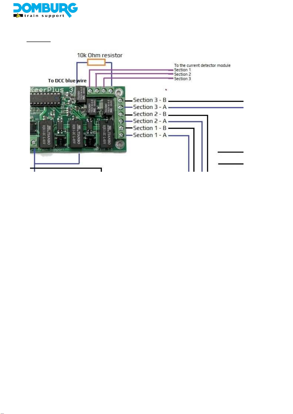
Detection
The switching outputs can also be used for a busy reporting module for control via software.
As you can see on the bottom of the module on the picture, the black conductor (DCC-B) goes to the
DR4088LN busy reporting module. That can be any other busy reporting module on the market. This is
independent of the DCC connection as written in section 3.2. This is necessary for the operation of the
module itself.
However, what is important is that the other conductor (DCC-A on the diagram) is brought to terminal 9
on the KeerPlus3. The reason that it should be the other polarity if the person you offer on the busy
reporting module is because the busy reporting module in this case does not feed the section as normal,
but only detects it.
You connect this dcc polarity to the terminal 9 with a carbon resistor with the value 10 kOhm (10,000
Ohm). Only this value will generate a detection on your busy reporting module. The resistor can
optionally be ordered with the KeerPlus3 in our webshop. You then bring the terminals 10/11/12 (S1 / S2
/ S3, respectively) with a wire to one of the outputs on the busy reporting module. Incidentally, it is not
mandatory to use all 3 detectors, this has no influence whatsoever on the operation of the KeerPlus3. The
outputs are electrically separated from the electronics on the module.
Autres manuels pour KeerPlus3
1
Table des matières
Autres manuels Domburg Matériel informatique


Manuels Matériel informatique populaires d'autres marques

EMC2
EMC2 VNX Series Manuel du propriétaire

Panasonic
Panasonic DV0PM20105 Manuel utilisateur

Mitsubishi Electric
Mitsubishi Electric Q81BD-J61BT11 Manuel utilisateur

Gigabyte
Gigabyte B660M DS3H AX DDR4 Manuel utilisateur

Raidon
Raidon iT2300 Manuel utilisateur

National Instruments
National Instruments PXI-8186 Manuel utilisateur


