dji ROBOMASTER Manuel utilisateur

v1.0
2020.01
Development Board Type C
User Manual

Searching for Keywords
Search for keywords such as “battery” and “install” to nd a topic. If you are using Adobe Acrobat
Reader to read this document, press Ctrl+F on Windows or Command+F on Mac to begin a
search.
Navigating to a Topic
View a complete list of topics in the table of contents. Click on a topic to navigate to that section.
Printing this Document
This document supports high resolution printing.

© 2020 DJI All Rights Reserved. 1
Content
Disclaimer 2
Warning 2
RoboMaster Development Board Type C 2
Introduction 2
In the Box 3
Overview 3
Development Board 3
SWD Cable 4
2-Pin CAN Cable 4
4-Pin CAN Cable 4
Mounting the Board Type C 4
Function Description 5
Power Supply 5
Input Protection Circuit 6
Customizable LED 6
5V Port 7
BOOT Conguration Port 7
Micro USB Port 8
SWD Port 9
Buttons 9
Customizable I/O Port 10
UART Ports 10
CAN Ports 11
PWM Ports 12
DBUS Port 13
Digital Camera FPC Port 14
Buzzer 14
Voltage Detection 15
6-Axis Inertial Measurement Unit (IMU) 15
Magnetometer 16
Usage 17
Specications 17
Appendix 17

2© 2020 DJI All Rights Reserved.
Disclaimer
Thank you for purchasing the ROBOMASTERTM Development Board Type C (hereinafter referred to
as “Board Type C”). Read this disclaimer carefully before using this product. By using this product,
you hereby agree to this disclaimer and signify that you have read it carefully. Install and use this
product in strict accordance with all related documents. Users bear the responsibilities in all the
consequences caused by using this product. DJITM will not bear any legal responsibilities for any
damages due to improper use, installation, or modication.
DJI and ROBOMASTER are trademarks of DJI and its affiliated companies. Names of products,
brands, etc., appearing in this document are trademarks or registered trademarks of their respective
owner companies. This product and document are copyrighted by DJI with all rights reserved. No
part of this product or document shall be reproduced in any form without the prior written consent or
authorization of DJI. The nal interpretation right of this disclaimer is reserved by DJI.
This document and all other collateral documents are subject to change at the sole discretion of DJI.
For up to date product information, visit http://www.robomaster.com and click on the product page for
this product.
Warning
1. Connect the cables correctly by following the instructions in this document. Otherwise, the cables
or the Board Type C may be seriously damaged.
2. Make sure there are no short-circuits and all the cables are in good condition. DO NOT use cables
that have been damaged in any way.
3. Make sure to use the product in strict accordance with the specications listed in this document,
including those related to voltage and temperature. Failure to do so may reduce the product
service life or even lead to permanent damage.
4. To avoid physical damage, make sure to assemble the Board Type C correctly.
5. If you detect any ames, smoke, strange smells, or other abnormalities, disconnect the Board Type
C from the power source immediately.
6. DO NOT open the silicone case. Otherwise, foreign objects may fall inside and the performance of
the Development Board Type C may be negatively affected.
RoboMaster Development Board Type C
Introduction
Designed to work with the products of RoboMaster and other accessories, the compact Development
Board Type C uses a high-performance STM32 microcontroller chip and supports a wide range of
voltage inputs. The highly integrable Board Type C boasts an expansion interface, communication
interface, and high precision IMU sensors and features an anti-reverse connection and anti-
overvoltage protection. The Board Type C provides rich routines and can be widely used in elds
such as robotics competitions, research and education, and automation equipment.

© 2020 DJI All Rights Reserved. 3
2-Pin Cable × 1
4-Pin Cable × 1
SWD Cable × 1
Power Cable × 1
Board Type C × 1
In the Box
Overview
Development Board
111212 131314
16
15
123 4 5 6 7
8
9
10
9
9
17
No. Name Interface Description
1Customizable LED Tri-color LED
25V Port 5V laser port
3RST Button Reset button for STM32
4Micro USB Port Port for USB communication or rmware download in DFU mode
5BOOT Conguration Port Conguration port of BOOT0 and BOOT1
6SWD Port Port for SWD downloader to download programs
7KEY Button Customizable button
824V Power Input Port Power input
924V Power Output Port Power output
10 Customizable I/O Port Port that can be congured as IIC and SPI ports
11 3-Pin UART Port 3-Pin UART port
12 CAN2 Port 4-Pin CAN port
13 CAN1 Port 2-Pin CAN port
14 4-Pin UART Port 4-Pin UART port
15 PWM Port PWM output port x 7
16 DBUS Port DBUS remote controller receiver port x 1
17 18-Pin Digital Camera
FPC Port FPC port for DCMI

ROBOMASTER Development Board Type C User Manual
4© 2020 DJI All Rights Reserved.
Cable length: 450 mm; A: Positive electrode (Red); B: Negative electrode (Black)
A
B
SWD Cable
2-Pin CAN Cable
Cable length: 350 mm; A: CANL (Black); B: CANH (Red)
Cable length: 100 mm; A: SWDIO (Black); B: SWCLK (Black); C: GND (Black); D: 3.3 V (Black)
4-Pin CAN Cable
Cable length: 350 mm; A: CANL (Grey); B: CANH (Grey); C: GND (Grey); D: 5 V (Red)
Mounting the Board Type C
Refer to the dimensions in the gure below when mounting the Board Type C.
AB
DC
A
B
AB
DC
4− 5.00 4− 2.50
60.00
36.00
Unit: mm
14.50
5.60
16.30
XT30 Power Cable

ROBOMASTER Development Board Type C User Manual
© 2020 DJI All Rights Reserved. 5
On the Board Type C there are four mounting holes, each with an inner diameter of 2.5 mm and an
outer diameter of 5 mm. The holes are used to help mount the board onto structural components. As
shown below, the ESC Center Board 2 can be used as an extension port for the Board Type C.
(Note: Screws and copper pillars are not included.) Unit: mm
Function Description
Power Supply
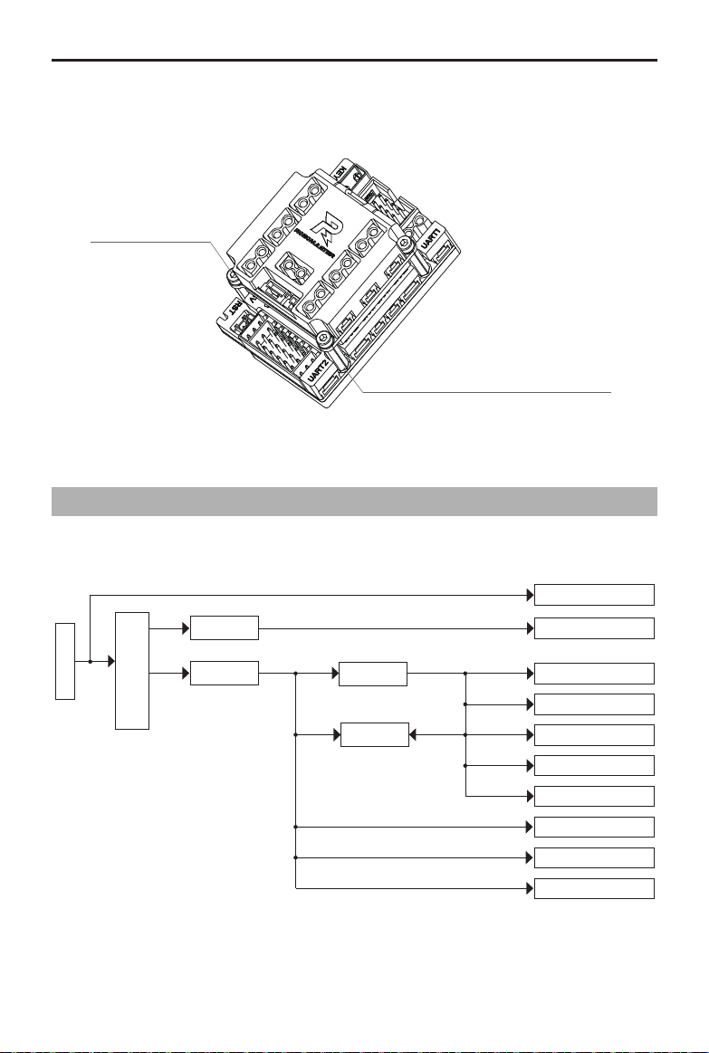
The Board Type C power supply block diagram is shown below.
The power supply of the Board Type C includes:
One 24 V to 5 V step-down circuit (power network VCC_5V_M), which is used for the seven external
PWM servo motor ports. The maximum total output current is 5 A.
M2.5-6 Screw (4 pcs)
M2.5-20 Double Pass Copper Pillar (4 pcs)
Power input
slow startup & reverse
connection protector
TPS54540
SY8510 5V@1A
24V
24V
5V@5A
5V@70mA 3.3V@1mA
3.3V@1A 3.3V@400mA
Power Output x 3
PWM Port x 7
STM32F407
IMU
IST8310
Digital Camera FPC Port
IIC & SPI Port
UART2
CAN2
5 V Port
3.3V@10mA
3.3V@5mA
3.3V@50mA
3.3V@250mA
5V@100mA
5V@100mA
5V@100mA
SY8089
TJA1044

ROBOMASTER Development Board Type C User Manual
6© 2020 DJI All Rights Reserved.
One 24 V to 5 V step-down circuit (power network VCC_5V), which is used for the onboard device
power supply and as the second input of power supply. The maximum output current is 1 A.
One 5 V (power network VCC_5V) to 3.3 V step-down circuit, which is mainly used for the onboard
device power supply.
Input Protection Circuit
The XT30 is adopted as the power input port for the Board Type C. The Board Type C prevents
reverse connection and slow startup, and with a built-in circuit for input overvoltage protection, it will
turn off the second circuit when the input is higher than 28 V.
Customizable LED
The Board Type C has a common anode RGB LED and the corresponding control IO is PH10 (Blue),
PH11 (Green), and PH12 (Red). When the output level of the IO port is high, the corresponding status
LED will be on. When the output level is low, the LED will be off. The brightness of the LED can be
adjusted via the PWM control.
LED_B
LED_G
LED_R
VCC_5V
R179
3.3KR
0402
R
G
B
D12
1
2
3
4
R107
10.0KR
0201
Q8
YJL3400A
G
S D
R106 1.0KR
0402
R177
2.0KR
0402
Q9
YJL3400A
G
S D
R108 1.0KR
0402
R178
5.6KR
0402
Q7
YJL3400A
G
SD
R110
10.0KR
0201
R101
10.0KR
0201
R100 1.0KR
0402

ROBOMASTER Development Board Type C User Manual
© 2020 DJI All Rights Reserved. 7
5V Port
The controllable 5V power port can be connected to the RoboMaster Red Laser Sight. The
corresponding switch control IO of the port is PC8. The brightness of the RoboMaster Red Laser Sight
can be adjusted via the PWM control.
TIM3_CH3
VCC_5V
R41
10K
0402
J5
53398-0271
1
1
2
2
33
44
Q4
YJL3400A
G
S D
R39 510R
0402
BOOT Conguration Port
The STM32 chip on the Board Type C has two pins: BOOT0 and BOOT1. The STM32 has three boot
methods and the level status of the two pins when the chip is reset determines the boot method after
the chip is reset. The Board Type C’s BOOT conguration schematic diagram is shown below.
BOOT1 BOOT0
VCC_3V3VCC_3V3
R165 10K
R1661.0KR
R64 10K
R167 1.0KR
J31
12
34
The level of the two BOOT pins is set to low by default. When powered on, STM32 boots from user
ash memory. The reset level status of BOOT0 and BOOT1 can also be congured using jumpers. As
shown below, the BOOT conguration pin is pinned out by using 2 x 2 rows of pin headers spaced 2.54
mm apart. For example, when BOOT0 = 1 and BOOT1 = 0, STM32 boots from the system memory
and enters DFU (Device Firmware Update) mode. Refer to the Micro USB Port section for more
information.
1 234

ROBOMASTER Development Board Type C User Manual
8© 2020 DJI All Rights Reserved.
The relationship between the STM32 boot method and BOOT conguration is shown below.
Boot Mode Selection Pins Boot Mode Aliasing
BOOT1 BOOT0
X 0 User Flash memory User Flash memory is selected as the boot space
0 1 System memory System memory is selected as the boot space
1 1 Embedded SRAM Embedded SRAM is selected as the boot space
Micro USB Port
A full-speed USB port is integrated in the Board Type C and can be used for USB communication with
other devices while also meeting USB 2.0 protocol specications. In primary mode, it supports full-
speed (FS, 12 Mbps) and low-speed (LS, 1.5 Mbps) transceivers. In secondary mode, only full-speed
(FS, 12 Mbps) transceivers are supported.
VCC5V_USB VCC_5V
USB_DM [4]
USB_DP [4]
USB_OTG [4]
C861uF
0402
D6
DSS34
3A
A C
L6
0603 1.4A
L12 NC
1 2
34
D9
PESD5V0F1BL
C A
R65
0.0R0402
D8
PESD5V0F1BL
C A
D7
PESD12VV1BL
AC
J7
1.0A
VBUS 1
DM 2
DP 3
ID 4
GND 5
SHELL1 6
SHELL2 7
SHELL3 8
SHELL4 9
SHELL5 10
SHELL6 11
R211 0.0R
0603NC
D35
PESD5V0F1BL
CA
R58
0.0R0402
C85100nF
0402
The USB port can be used to supply power for a Board Type C (only STM32 and some onboard
external devices can be driven by the USB port*) and download rmware in DFU mode with BOOT
conguration. Follow the steps below to download Board Type C rmware in DFU mode.
1. Set the level status of BOOT0 as high and BOOT1 as low using jumpers.
2. Connect the Board Type C to a computer using the USB cable.
3. Press the RST button to reset the Board Type C and enter DFU mode.
4. Convert the BIN le to a DFU le using the DFU File Manager.
5. Download the DFU le to the Board Type C using DfuSe Demo.
* USBpowersupplyisforpowernetworkVCC_5Vonly.OnboarddeviceslikethePWMexternalportpoweredby
powernetworkVCC_5V_Marenotsupported.
Autres manuels pour ROBOMASTER
3
Table des matières
Autres manuels dji Carte mère
Manuels Carte mère populaires d'autres marques

Telit Wireless Solutions
Telit Wireless Solutions SL869-3DR Manuel utilisateur

Gigabyte
Gigabyte GA-9IVDT Manuel utilisateur

Texas Instruments
Texas Instruments ADS8372EVM Manuel utilisateur

Commell
Commell MS-C73 Manuel utilisateur

IBT Technologies
IBT Technologies MB860 Manuel utilisateur

Nvidia
Nvidia TEGRA DG-04927-001_V01 Manuel utilisateur