DF ROBOT BLE4.1 Manuel utilisateur

DFRobotBLE4.1ModuleSKU:TEL0120
Introduction
BLE4.1 Module is DFRobot newly developed Bluetooth 4.1 transmission module, adhering to the
same usage of Bluno, and increasing the star network function, KISS connection (Approach
Connection). The new Bluetooth is designed based on BLE 4.1 technology. It has low power
consumption and other special features. In the BLE transmission, the point-to-point output rate is
4Kbps, equivalent to the original Bluno twice the rate.
BLE4.1 Module uses DA14681 high-performance BLE chip, it integrates advanced power
management system, coming with 3.7V lithium battery charging circuit. It obtains power directly from
the USB port. Support 400mA maximum charge current,
Feature
Support BLE 4.1 master and slave switch
Support Bluetooth serial data transmission
Support Bluetooth point-to-point wireless programming
Support Bluetooth 4.1 multi-device cascade (up to 4)
Support Arduino Bluetooth library (support for multi-Bluetooth connection)
Support low power consumption Bluetooth (standby 25uA; interrupt 70uA)
Two-way interrupt wake up:
* BLE4.1 wake up controller via P4_2 (high level wake up)
* The controller wakes up BLE4.1 via WAKEUP (low level wake)
Support KISS connection method (Approach Connection)
Support Bluetooth firmware update
Support lithium battery powered
Support USB to charge the lithium battery
LED status indicator

Specification
Processor: DA14681 (ARM Cortex-M0 CPU)
Operating Voltage: 3.3V
USB input Voltage: 4.2V ~ 5.0V
Lithium battery powered: 3.7V
Support USB charging (chip comes with charging function)
Charging current: 10mA ~ 400mA (max)
Allow external lithium battery capacity: 20mAh ~ 500mAh (max)
Supports low power consumption: only 30uA / MHz minimum 2uA
Single I / O port maximum output current: 4.5mA
Allows I / O port maximum output total current: 100mA
Supports three network connection modes (P2P connection, star network, tree network [Developing])
Maximum number of slave connections: 4 (simultaneous connection)
Maximum transfer rate of 4Kbps
Flash: 8Mbit
64KB OTP
128KB Data SRAM
16KB Cache SRAM
128KB ROM
On-chip crystal: 16MHz, 32.768KHz
Three power management modes: Extended sleep, Deep sleep, Hibernation
29 digital I / O ports
8 analog inputs
1 SPI
2 I2C (supports 100KHz and 400KHz two communication rates)
2 UARTs
6 PWM
I2S / PCM master-slave interface
IR interface (PWM)
Support USB1.1 (computer-side simulation into a serial port)
Built-in temperature sensor
Transmit power consumption: 3.4mA (TX) 3.1mA (RX)
Operating temperature: -40 ~ +85
Dimension: 25 * 18 * 3 mm/ 0.98 * .70 * 0.11 inches
Layout
Fig1: DFRobot_BLE4.1_Module PinOUT

Fig2: DFRobot_BLE4.1_Module PinMap
Note: VBUS and GND are USB Power port; BAT+ and BAT- are battery power po
rt.
Note: There is a 0.1 ohm resistor between BAT- and GND. The battery can also be
used directly between BAT + and GND when in use
Dimension
Dimension: 25 × 18 x 3 mm
Fig3: DFRobot_BLE4.1_Module Dimension

ATCommand
To get a ‘better’ Bluetooth experience on BLE 4.1 modules, we highly recommand you to
update the newest firmware first.
AT is the abbreviation of attention. AT command is the communication command used to configure
Bluetooth parameters. It begins with AT, end with <CR+LF> (carriage return and line feed).
NOTE: <CR+LF> is not a part of AT Command.
ATCommandList
AT Command Function Parameters <X>
A
T+ROLE=<X> Set Bluetooth
mode
“?” Query Bluetooth working mode
“ROLE_CENTRAL” Set as the central device
“ROLE_PERIPHERAL” Set as the peripheral device
A
T+NETWORK=<X> Set network
mode
“?” Query the network mode
“P2P” Set to peer to peer connection
“STAR” Set to star network
A
T+MIN_INTERVAL=<X>
Set the
minimum
communication
interval
“?” Query the current minimum communication interval (10~99999ms)
A
T+MAX_INTERVAL=<X>
Set the
maximum
communication
interval
“?” Query the current maximum communication interval (10~99999ms)
A
T+BIND=<X> Set binding
Bluetooth
address
“?” Query the current binding MAC address
e.g.: 0x0017ea9397e1 Set Bluetooth MAC address in need
A
T+CMODE=<X> Set BLE
connection
mode
“?” Query the current connection mode
“UNIQUE” Specify the connection mode
“ANYONE” Set to free connection
A
T+MAC=<X> Query the
Bluetooth
address “?” Query the current Bluetooth MAC address
A
T+NAME=<X> Set the name “?” Query the Bluetooth device name
“DFBLEduino2”
A
T+SETTING=<X> Modify/Reset
to default <X>
mode
“?” Query the current setting
“DEFAULT” Reset to initial setting
“DEFPERIPHERAL” Reset to initial slave setting
“DEFCENTRAL” Reset to initial host setting
A
T+USB_MONITOR=<X> Turn the USB
monitor
ON/OFF
“?” Query the current USB monitor
“ON” Turn on the USB monitor

“OFF” Turn off the USB monitor
A
T+HELP=<X> Get help from
A
T command “ALL” Query all AT commands help information
A
T+NET_INF=<X>
Query device
information in
the current
network
“?” Query device network information
A
T+VERSION=<X> Query the
firmware
version “?” Query firmware version information
A
T+RSSI=<X> Query the
RSSI value “?” Query the RSSI value
A
T+P<n>=<X>
Query & Set
P(n,
n=0,1,2,3...)
status
“?” Set IO pins to input mode and query the voltage
“1” Set IO pins to output mode and output HIGH voltage
“0” Set IO pins to output mode and output LOW voltage
A
T+WL=<X> Query/Declare
the White List “?” Query the White List
“NONE” Declare the White List
A
T+LOWPOWER=<X> Query & Set
the low-power
mode
“?” Query the low-power mode
“ON” Turn on the low-power mode
“OFF” Turn off the low-power mode
A
T+EXIT Exit the AT
command
mode Exit the AT command mode
ConfiguretheBLEthroughATcommand
1. Open the Arduino IDE.
2. Select the correct serial port in Menu->Tool->Serial port
3. Open the Serial monitor (on the upper right of the IDE windows)
4. Select the "No line ending"(①) and 115200 baud(②) in the pull-down menu
5. Type "+++"(③) like this and press send button(④)
6. If the AT Command Mode is successfully access , you will receive "Enter AT Mode"(⑤) from it.

Fig1: +++ enter the AT CMD Mode
7. Select the "Both NL & CR"(①) and 115200 baud(②) in the pull-down menu
8. Type or copy the AT command in the dialog(③) like this and press send button(④)
9. If the BLE is successfully configured , you will receive "OK"(⑤) from it.
Fig1: enter the AT command,remember selecting the Both NL & CR
10. If received "ERROR CMD" instead, try sending it again or you should check whether the
command is correct or not.
11. USE “AT+EXIT” to exit AT Mode
12. You can input AT+HELP=ALL to query all AT Command information

Fig1: Enter AT+HELP=? to get AT Command List
BluetoothConnection
Before using BLE4.1 series devices, it is better to know some key buttons first.
BOOT: Update Bluetooth firmware/Enable the approach connection (<10cm).
Firmware update**: Press and hold the "BOOT" button until you plug USB cable, entering firmware
update mode. For any enquiry, please refers to the part: Firmware Update. (You can release your
hand after you plugged the USB cable.)
Approach connection**: Press and hold the host BOOT button, approach the slave Bluetooth
device to connect.
WAKEUP: the button can wake up the device from low-power consum[ption mode (you can also
connect this pin to MCU to realize the same function)
RST: BLE4.1 reset button
Below is the BLE4.1 minimum system circuit diagram for your reference: Fig1: the BLE4.1
minimum system circuit diagram

Fig1: BLE4.1 Minimum System Schematic
SmartphoneBluetoothConnection
Android Terminal and IOS Terminal
BlunoBasicDemo Android, Android source code (DFRobot)
LightBlue IOS
Blynk IOS
Different from the traditional Bluetooth (such as Bluetooth headset), BLE4.1 need specified
eigenvalue and device service ID to connect smartphone. The direct connection between BLE and
smartphone device manager will lead to communication problems. Therefore, it needs a the third
party APP, such as BunoBasicDemo (published by DFRobot), BLE Device Monitor from TI .etc.
In this section, we'll take BunoBasicDemo published by DFRobot as an example.
Set BLE4.1 as peripheral device with command AT+ROLE=ROLE_PERIPHERAL. Set connection
mode as P2P by AT+NETWORK=P2P command and restart BLE4.1 (power off and restart).
Open BunoBasicDemo app, click SCAN, then we'll see the scanned BLE4.1 device .
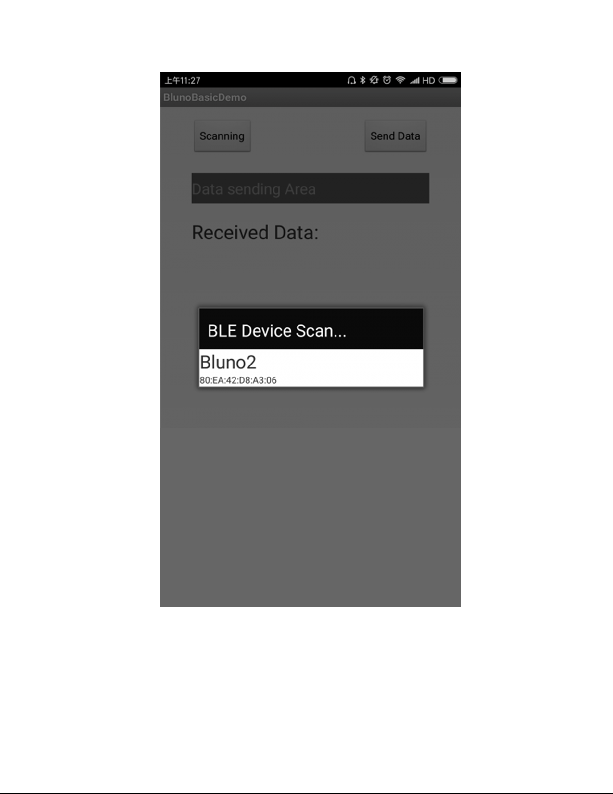
Fig1: Scanning
Click the device to connect. Once it connected successfully, it will show Connected and LINK will
light for 3s and blink for every 3s.

Fig2: Connected
Send data frome the Data sending Area
Ce manuel convient aux modèles suivants
1
Table des matières
Autres manuels DF ROBOT Unité de contrôle

DF ROBOT
DF ROBOT TEL0070 Manuel utilisateur

DF ROBOT
DF ROBOT DFPLayer Mini Manuel utilisateur

DF ROBOT
DF ROBOT SEN0521 Manuel utilisateur

DF ROBOT
DF ROBOT TEL0097 Manuel utilisateur

DF ROBOT
DF ROBOT DFR0699 Manuel utilisateur

DF ROBOT
DF ROBOT DS1307 Manuel utilisateur

DF ROBOT
DF ROBOT TEL0051 Manuel utilisateur
Manuels Unité de contrôle populaires d'autres marques

Festo
Festo Compact Performance CP-FB6-E Manuel de la liste des pièces

Elo TouchSystems
Elo TouchSystems DMS-SA19P-EXTME Manuel utilisateur

JS Automation
JS Automation MPC3034A Manuel utilisateur

JAUDT
JAUDT SW GII 6406 Series Guide rapide

Spektrum
Spektrum Air Module System Manuel utilisateur

BOC Edwards
BOC Edwards Q Series Manuel utilisateur


