IOLITEiw-3xMEMS-ACC
INSTALLATION MANUAL
The following configurations include an external power injector which is necessary due to voltage drop
in case of long chains. The configurations are presented in the order from the most recommended to
the least recommended in terms of EMI immunity.
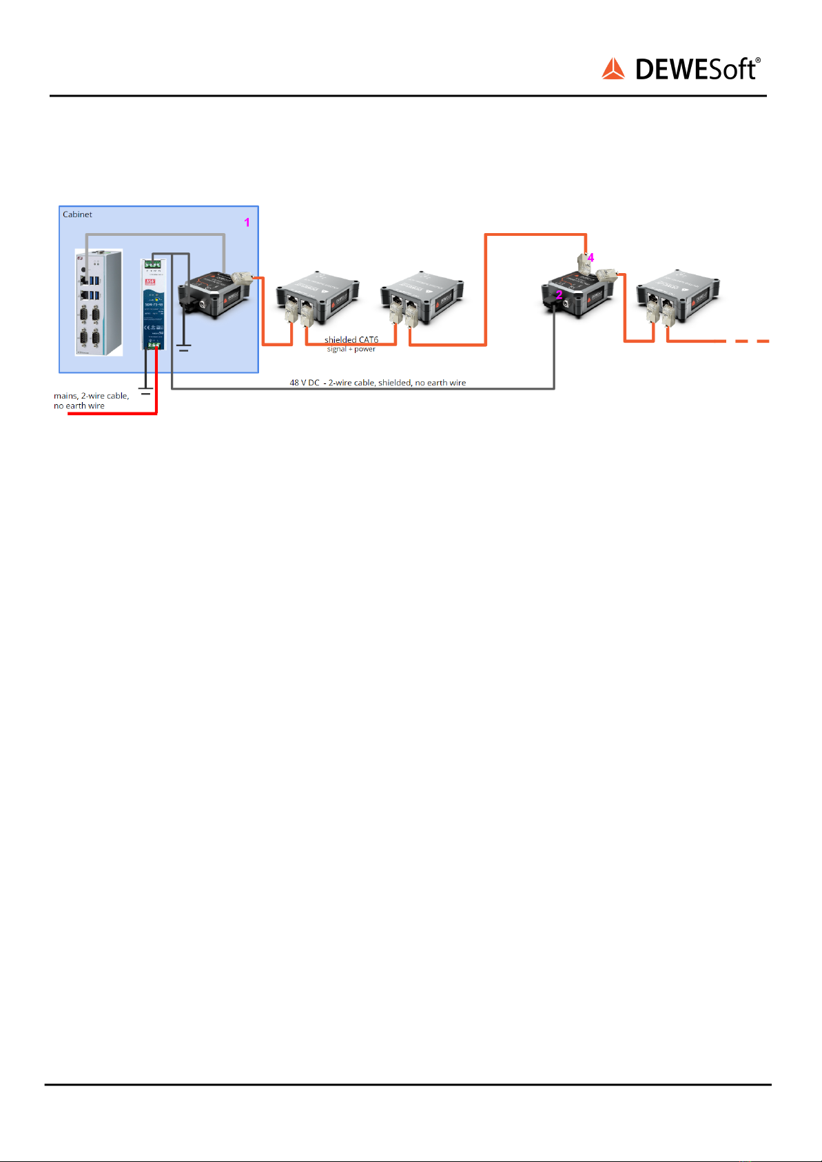
Multiple power injectors, non-conductive structure (i.e. concrete bridge),
AC line to external power supply, local earth available
This schematic shows the most recommended wiring in case external power injectors need to be used.
The industrial PC, Ethercat power supply and power injector are typically inside the main electrical
cabinet (1), together with appropriate surge protection for the power supply system used on installation
site (TN or TT).
If additional external power injector (2) is needed (due to voltage drop in a long chain), it is
recommended that it is powered by a local power supply (3) which means the main AC line needs to be
wired to it. This is the most robust wiring against EMI disturbances.
The external power injector and power supply must both have the EARTH pins connected locally. It is
necessary to perform resistance measurement between the EARTH terminals and local earthing point
according to EN-60364 to ensure functionality (i.e. <0.1 ohm resistance at 10 A test current).
To avoid a ground loop, it is important to break the daisy chained network cable shield by placing an
unshielded RJ45 connector (4) at the IN port of the external power injector.
To protect external power supplies from lightning strike, it is recommended that surge protection (6) is
added to each external power supply.
Note on conductive structures (i.e. steel bridge): if the structure is conductive, the shield needs to be
broken at every device’s IN port as explained in the previous section.
IOLITEiw-3xMEMS-ACC installation manual V23-2 7/29