Dembla 8100F21 Series Manuel utilisateur

Instruction Manual
Floating Ball Valve
Series-8100F21
0062
2 G/D T 3/4/5/6
1Feb 2009

CONTENTS PAGE NO.
1.0 Foreword 2
1.1 Scope of Instruction Manual 2
1.2 Copyright and Modification Rights Reservation 2
1.3 Safety Instructions 2
2.0 Introduction 3
3.0 Installation of 'O' Ball Valve 3
3.1 Pre-Installation Checks 3
3.2 Operation 3
3.3 Lubrication 3
3.4 Replace Gland Packing & Seat Ring. 4
4.0 Recommended Spares (for 'O'-ball valve) 5
1

1.0 Foreword
1.1 Scope Of Instruction Manual
This Instruction Manual covers information regarding Installation and Maintenance of
Dembla's Floating ball Valve.
1.2 Copyrights And Modification Rights Reservation
Dembla Valves Ltd. retains the copyright on the contents of this Instruction Manual.
The Total content of this instruction manual described here corresponds to the
information during preparation of the instruction manual. It is user's responsibility to refer the latest version.
All data, specifications and illustrations here are subjected to technical modifications and improvements and
hence modification can be done by us at by time without any prior notice. No claim to modification or repair
of these valves, which have already been supplied by us, can be made.
1.3 Safety Instructions
1) Before attending to Valve Installation / Maintenance, the instruction manual must be
compulsorily read and understood properly.
2) Valve must be operated by qualified personnel.
3) Ensure that the operator handling these Valves must follow Safety Instruction.
4) Ensure that before opening the valve for maintenance or repair, wear suitable protection
when dealing with hazardous process fluids.
5) All Safety Messages such as Cautions, Warnings and Notes are highlighted in this
Instruction Manual which must be strictly followed to avoid any possibility of arising
danger / risk of damage to the equipment / person's life.
6) No Liability on Manufacturer for any wrong handling, improper commissioning and
wrong assembly.
7) No modification / conversions are allowed without written authorization from Dembla
Valves Ltd.
2.0 Introduction
Dembla's Floating Ball valves are available conforming design as per
BS – 5351
EN-17292
API6D
2

3.0 Installation Of 'O' ball Valve
3.1Pre-installation Checks: (Before installing any 'O' Ball Valve)
(1) Inspect it for any shipment damage and for foreign material that might have collected
during packing and shipment.
(2) Blow out all pipelines to remove pipe scale-chips, welding-slag, and other foreign
materials.
(3) Install the valve using accepted piping practices.
(4) Install the valve according to flow direction marked on the valve.
(5) Use self centering gasket.
(6) Install the valve preferably in a straight run of pipe away from bends or sections of
abnormal velocity.
(7) Incorrect pipe alignment will cause interference between the Ball surface and soft seat,
excessive torque and damage to ball and soft seat, resulting into seat leakage.
(8) Do not try to install valve between line flanges having inadequate gap. This may cause
damage to some valve parts.
(10)Glands are factory tightened and checked for leakage however if there is any gland
leak in valves, the gland may be further tightened just enough to stop leakage.
Excessive tightening should be avoided.
3.2 Operation
Valve closes with clockwise rotation of the valve shaft. The limit position are set in the
operators for extreme condition i.e open & close.
3.3 Lubrication
For manual operator, lubrication is required.
3

3.4 Replace Gland Packing & Seat Ring.
1) Loosen & remove locknut(15) & lock pins(10).
2) Remove lever (9)
3) Remove lock washer (14)
4) Loosen & remove second lock nut (15)
5) Remove lock plate (11) & gland bush (13)
6) Remove gland packing (8)
7) Loosen & remove body stud nut (4)
8) Remove side connection (2) along with soft seat (6)
9) Slide the ball (3) outword & remove it.
10)Remove valve shaft (5) from inside of valve body (1)
11)Remove thrust washer(12)
12) Clean all parts & keep in clean & dry space.
13) Replace soft seat (6) from both side connection (2)
14)For assembly use reverse sequence.
4.0 Recommended Spare (for “O” Ball Valve)
It is recommended to stock following spare parts for commissioning and routine service:
4

5
5.0 To Separate Actuator from Valve Body.
Before starting disassembly.
Use Bu-pass Valve pr completely shut off the process to isolate the valve from pressure. Drain fluid
from both ends of the Valve.
If the Valve Opens with Pneumatic signal pressure to Actuator, remove air from the Actuator before
attempting to remove Valve from line.
While dismantling the valve, if any port is stuck up, do not use any pressure or force Technique. Use
proven methods only.
Unscrew the Bracket Bolts from valve assembly.
Unscrew & remove the Mounting Bracket and actuator along with Accessaries.
Remove the Pinion Shaft from Valve Shaft
6
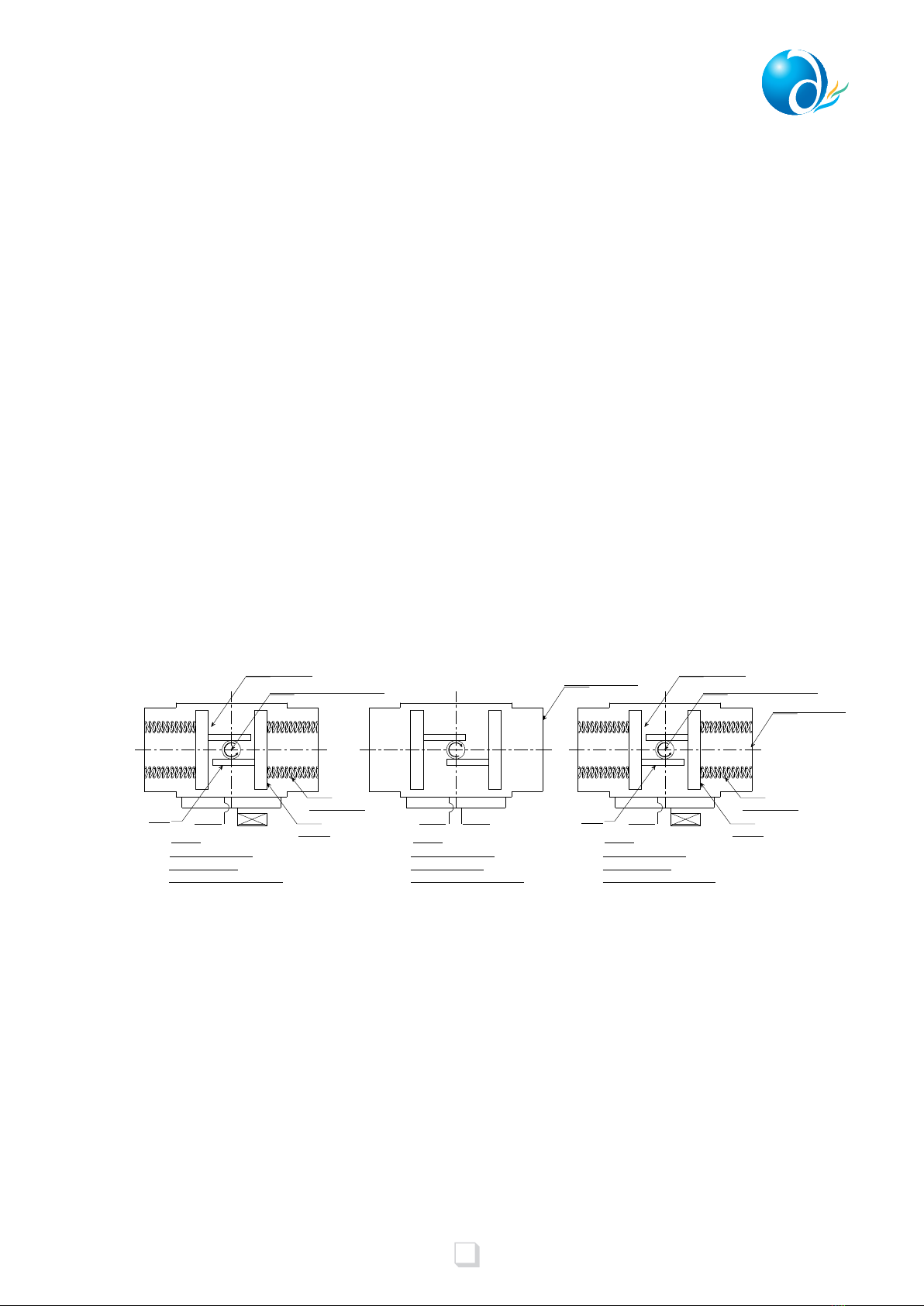
6.0 Actuator Operation
The Actuator Drive Shaft rotates through a full 90°. Rotation is accomplished be
feeding supply air into the center chamber(through Port A) forcing the two opposing
Piston outword, remaining in counter-clockwise rotation of the Drive Shaft to the
‘Open’ position.(Refer Fig. A)
For closure is accomplished by means of Springs contained in the end cap chambers,
which force the Piston inward when the supply air to the center chamber (Port A) is
allowed to exhaust. (Refer Fig. A)
For double-acting Actuators, Rotation is accomplished be feeding supply air into the
center chamber ( through Port A ) forcing the two opposing pistons outward, resulting
in counter-clockwise rotation of the Dive Shaft to the ‘Open’ position, for closure is
obtained by feeding supply air into the end cap chambers (through Port B) which
forces the Piston inward, resulting in clock-wise rotation of the Drive Shaft. (refer
Fig.B.)
To reverse the stroke direction of the Actuator, remove both Piston, rotate them by
180° and re-install. This will reverse the direction of rotation of the output shaft. (refer
Fig. C)
ACTUATOR ASSLY.
DOUBLE ACTING
(OPEN-CCW & CLOSE-CW)
ACTUATOR ASSLY.
SINGLE ACTING
(OPEN-CCW & CLOSE-CW)
Port-A Port-B Port-A Port-B
Drive shaft with pinion gear
Center chamber
Pistons
Piston spring
End cap chamber
ACTUATOR ASSLY.
SINGLE ACTING
(OPEN-CW & CLOSE-CCW)
Port-A Port-B
Center chamber
Pistons
Piston spring
End cap chamber
(FIG.A) (FIG.B) (FIG.C)
Rack Rack
Drive shaft with pinion gear

7
In the event of air failure, the Actuator can be cycled manually, This is accomplished by
applying a wrench to the exposed tap shaft of the Actuator and turning it in the desired
direction. This is not recommended on Model PD500/PE280 and larger size of Actuators.
For these, Dembla Valves Limited offers optional Manual Over-ride Gear units, with
declutch able hand wheels. ( Not Shown).
CARE MUST BE TAKEN TO ENSURE THAT THE ACTUATOR IS NOT OPERATED
AUTOMATICALLY THROUGH AIR SUPPLY WHILE MANUAL OPERATION IS BEING
PERFORMED !
Is is recommonded to stock the following spares parts for commissioning and routine
service.
Note : While ordering spares, please do not miss to indicate ‘Valve Serial No.’
Appearing on nameplate fixed on the actuator Valve Serial No. also appears on the
Valve Body dully punched. The Valve serial No. beings with prefix V, eg V-
12345.........
7.0 Manual Operation
8.0 Torque for Studs
9.0 Recommended Spares
Studs
5/16”
3/8”
1/2”
5/8”
3/4”
Torque Nm
5
7
30
50
170
PART NAME
RECOMMENDED QUANTITY
Seat Ring
Gasket Body to
Side Connection
Gland Packing
One Set for every valve
One set of 'O' Ring for every five valve
One set of 'O' Ring for every five valve
One set of gasket for every five valve
SR. NO.
1
2
3
4
!Note

8
10.0 Parts Illustrated (Floating Ball Valve With Rotary Actuator)
PART NAME
RECOMMENDED QUANTITY
Seat Ring
Gasket Body to
Side Connection
Gland Packing
One Set for every valve
One set of 'O' Ring for every five valve
One set of 'O' Ring for every five valve
One set of gasket for every five valve
SR. NO.
1
2
3
4

9
Disassembly of Floating Ball Valve:
1. Loosen and remove the Hex Bolts (Actuator-MOR) .
2. Pull and remove the Actuator from top side.
3. Loosen and remove the Hex Bolts (MOR-Bracket) .
4. Remove MOR .
5. Remove Pinion Shaft .
6. Loosen and remove the Hex Bolts (Body-Bracket) .
7. Remove the Bracket .
8. Loosen and remove Lock Nut .
9. Remove Gland Bush .
10. Remove Gland Packing ( .
11. Loosen and remove Body Nut .
12. Remove Side connection along with Soft Seat and Gasket .
13. Slide the Ball outward and remove it.
14. Remove Valve Shaft from inside of Body .
15. Remove Thrust Washer .
16. Clean all parts and keep in clean and dry space.
17. Remove Soft Seat from both Side Connection if required.
18
15
17
14
13
16
12
11
11
8
4
6
3
5
9
6
7
1
2
11.00 Disassembly & assembly Procedure of Floating Ball Valve
2
Table des matières
Autres manuels Dembla Unité de contrôle


Manuels Unité de contrôle populaires d'autres marques

Festo
Festo Compact Performance CP-FB6-E Manuel de la liste des pièces

Elo TouchSystems
Elo TouchSystems DMS-SA19P-EXTME Manuel utilisateur

JS Automation
JS Automation MPC3034A Manuel utilisateur

JAUDT
JAUDT SW GII 6406 Series Guide rapide

Spektrum
Spektrum Air Module System Manuel utilisateur

BOC Edwards
BOC Edwards Q Series Manuel utilisateur


