Creotech FMC masterFIP Manuel utilisateur

FMC masterFIP
Production Test Suite
User Manual
Creotech Instruments SA | Jan 2018 | Version 4.0

- 1 -
Revision Table
Revision
Date
Author
Comments
4.0
31/01/2018
Eva Gousiou
Update to board version V4: changed log
folder name, ipmi part: EDA-03098-V4.
3.0
08/03/2017
Marek Gumiński
Update to board version V3: removed ADC
tests, modified EXT_SYNC tests.
2.0
16/11/2016
Evangelia Gousiou
Changes for V2 version of the board (removed
EXT_SYNC_TST)
1.0
11/07/2016
Marek Gumiński
Implemented CERN suggestions
0.1
01/06/2016
Marek Gumiński
Initial version.

- 2 -
Table of content
1. Introduction.................................................................................................................................... - 3 -
2. FMC masterFIP Board Functionality ............................................................................................... - 9 -
3. PTS Functionality Tests ................................................................................................................. - 10 -
4. Log files retrieval .......................................................................................................................... - 11 -
5. Custom cable preparation ............................................................................................................ - 12 -
6. First Time Setup............................................................................................................................ - 13 -
7. Testing Procedure......................................................................................................................... - 15 -
8. Common Causes of Test Failure ................................................................................................... - 17 -

- 3 -
1. Introduction
Welcome to the Production Test Suite for the FMC masterFIP board –FMC masterFIP PTS.
The FMC masterFIP Production Test Suite (PTS) is an extension of the original PTS which allows to
perform functionality tests on FMC masterFIP boards after manufacturing. The original PTS was intended
for testing boards designed for the Open Hardware Repository, but it proved to be adaptable to other
boards. It assures that the boards comply with a minimum set of quality rules, in terms of soldering,
mounting and fabrication process of the Printed Circuit Boards (PCB).
It is important to note that the FMC masterFIP PTS covers only to the functionality tests of the boards
and does not cover any verification or validation tests of the design. This document describes the FMC
masterFIP PTS components and its use.
Figure 1: FMC masterFIP PTS view

- 4 -
The main elements of the PTS are listed in Table 1.
Table 1: FMC masterFIP PTS elements
Item
Comments
Computer
A computer based on motherboard with 4 line PCIe slots is required
Monitor
Keyboard, Mouse
Barcode reader
With USB connection to the computer
ESD wrist strap
With banana type connection to the computer chassis
PCIe extender cable
Two spacers and four screws to fix the PCIe extender board to the
computer case
SPEC board
Four spacers and height screws are used to fix the board to the
computer case
FMC masterFIP
Board under test
1x LEMO cable
Any length, min 2 ns recommended
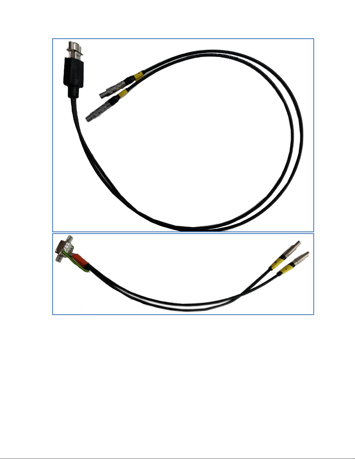
1x LEMO –Dsub9 custom cable
Schematic shown in Figure 9, picture of real component in Figure 6
1x LEMO –miniDsub9 custom
cable
Schematic shown in Figure 9, picture of real component in Figure 6
nanoFIPDiag
nanoFIPdiag version must match FMC masterFIP under test speed
version.
http://www.ohwr.org/projects/nanofipdiag/wiki
USB relay box 1
FMC Fine Delay version. USB cable provided
http://www.ohwr.org/projects/usb-relay-box1/wiki
Documentation
This user guide plus the one-page testing procedure
In terms of software, the computer is equipped with the following:
Table 2: PTS software requirements
Ubuntu Linux 14.04.00 LTS
Python 2.7
The user login is:
Table 3: Computer login
Username
user
Password
baraka
Note that after the software installation the computer should be disconnected from the network and no
updates should be allowed.

- 5 -
The following paragraphs provide an overview of the required items.
The FMC masterFIP mezzanine board is tested while mounted on a SPEC carrier board, as Figure 2 shows.
The SPEC carrier board provides access to the PCIe interface of the computer. The computer hosts the
FMC masterFIP PTS software which provides the automated testing environment.
Figure 2: SPEC-DAC-DDS combination
To facilitate the testing setup, the SPEC carrier is fixed on the computer’s box and a PCIe extender cable
is used.
Figure 3: SPEC connected to the PCIe extender

- 6 -
The Relay Box (fine delay version) is controlled by PTS software in order to automate cable
reconnections.
Figure 4: USB relay box 1
The nanoFIPdiag is used to verify the WorldFIP bus communication by answering to WorldFIP question
frames. Note that the nanoFIPdiag speed version should match the version of the masterFIP under test.
Figure 5 nanoFIPdiag
- 7 -
Custom cables are used to connect the FMC masterFIP to the nanoFIPdiag via the USB relay box.
Figure 6 Custom cables
One standard Lemo00-Lemo00 cable is also required. Any length may be used.

- 8 -
The test setup is shown on Figure 7.
Figure 7: Test setup connections. LEMO-LEMO cable is marked red. Custom LEMO-miniDsub9 is marked blue. Custom
LEMO-Dsub9 is marked green.
The complete duration of the test is around five minutes.
In brief, the operator needs to:
omount the FMC masterFIP board onto the SPEC carrier
oconnect the cables between the FMC masterFIP, the USB relay box and the nanoFIPdiag
orun the software
oat certain points of the tests an intervention needs to be done by the operator (e.g.: scan the
board’s barcode, check the font panel LED); the interventions are explicitly signaled by the FMC
masterFIP PTS software and this manual.
At the end of the functionality tests the operator receives a PASS/FAIL notification. In case of a FAILED
board, information is provided on the failing components.
All test results are automatically saved in a folder on the computer.
A board is considered to have passed the PTS testing if it has successfully completed all the functionality
tests.
For a FAILED board, you can repeat the test only one more time! If a board FAILs twice, please report to
the CERN responsible.
- 9 -
2. FMC masterFIP Board Functionality
FMC masterFIP is an interface card for the WorldFIP network in an LPC FMC form-factor.
WorldFIP is a deterministic rad-tol fieldbus used at CERN's LHC for a variety of control systems.
Cryogenics, Power Converters, Beam Instrumentation and other critical systems are using WorldFIP for
the exchange of data between their sensors and actuators and the control and supervision level. With
Alstom phasing out WorldFIP support in 2009, it was decided to insource this technology at CERN.
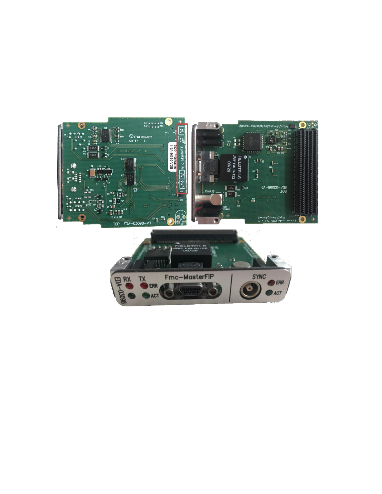
Figure 8: Bottom, top and front views of the masterFIP board
The FMC masterFIP mezzanine board is tested while mounted on a SPEC carrier board. The SPEC provides
FPGA logic, power supplies, memories, clocking resources and interface to the PCIe bus. The mezzanine
houses all the WorldFIP specific parts (FielDrive, FieldTR).
There are four different versions of masterFIP boards that correspond to the four different WorldFIP
speeds: 31.25 Kbps, 1 Mbps, 2.5 Mbps and 5 Mbps. One can visually distinguish the version by checking
the on the resistor indicators on the bottom side of the board as Figure 8 shows.
Table des matières
Manuels Matériel informatique populaires d'autres marques

EMC2
EMC2 VNX Series Manuel du propriétaire

Panasonic
Panasonic DV0PM20105 Manuel utilisateur

Mitsubishi Electric
Mitsubishi Electric Q81BD-J61BT11 Manuel utilisateur

Gigabyte
Gigabyte B660M DS3H AX DDR4 Manuel utilisateur

Raidon
Raidon iT2300 Manuel utilisateur

National Instruments
National Instruments PXI-8186 Manuel utilisateur


