Coven 10 EMX USL Manuel utilisateur
SPARE PARTS DIAGRAM FOR
First Choice Group
Blakeney Way, Kingswood Lakeside
Cannock, Staffs, WS11 8LD
TEL: 01543 577778 FAX: 01543504141
Email: [email protected]
Web: www.firstchoice-cs.co.uk
Combination Oven
10-EMX-USL
STEAM OVEN WITH BOILER
10 EMX USL
INSTALLATION, USE AND MAINTENANCE MANUAL

1
CONTENTS
Oven installation diagram ........................................................................ pag. 2
1. Place of installation.............................................................................. pag. 3
2. Installation............................................................................................ pag. 3
3. Connection to supply system............................................................... pag. 3
4. Water connection................................................................................. pag. 3
5. Connection to water drain .................................................................. pag. 3
6. Oven start-up....................................................................................... pag. 4
7. Controlling the functions ...................................................................... pag. 4
Wiring diagram – Fig. 1 .......................................................................... pag. 5
Wiring diagram key.................................................................................. pag. 6
TABLE 1 – Technical features................................................................. pag. 7
Instructions for the user – Fig. 2 ............................................................. pag. 8
Operating instructions.............................................................................. pag. 9
Maintenance suggestions........................................................................ pag. 10
Operating suggestions............................................................................. pag. 10
Control Panel........................................................................................... pag. 11
Steam cooking super – Fig. 3 ................................................................. pag. 12
Steam cooking with adjustable temperature 0-99°C – Fig. 3................... pag. 12
Mixed cooking convection + steam – Fig. 3 ............................................ pag. 13
Dry convection cooking – Fig. 3 .............................................................. pag. 13
Quick cooling – Fig. 3 ............................................................................. pag. 14
Food thawing, core temperature probe.................................................... pag. 15
Washing instructions (optional) ............................................................... pag. 15,16
Delayed cooking ..................................................................................... pag. 17
2
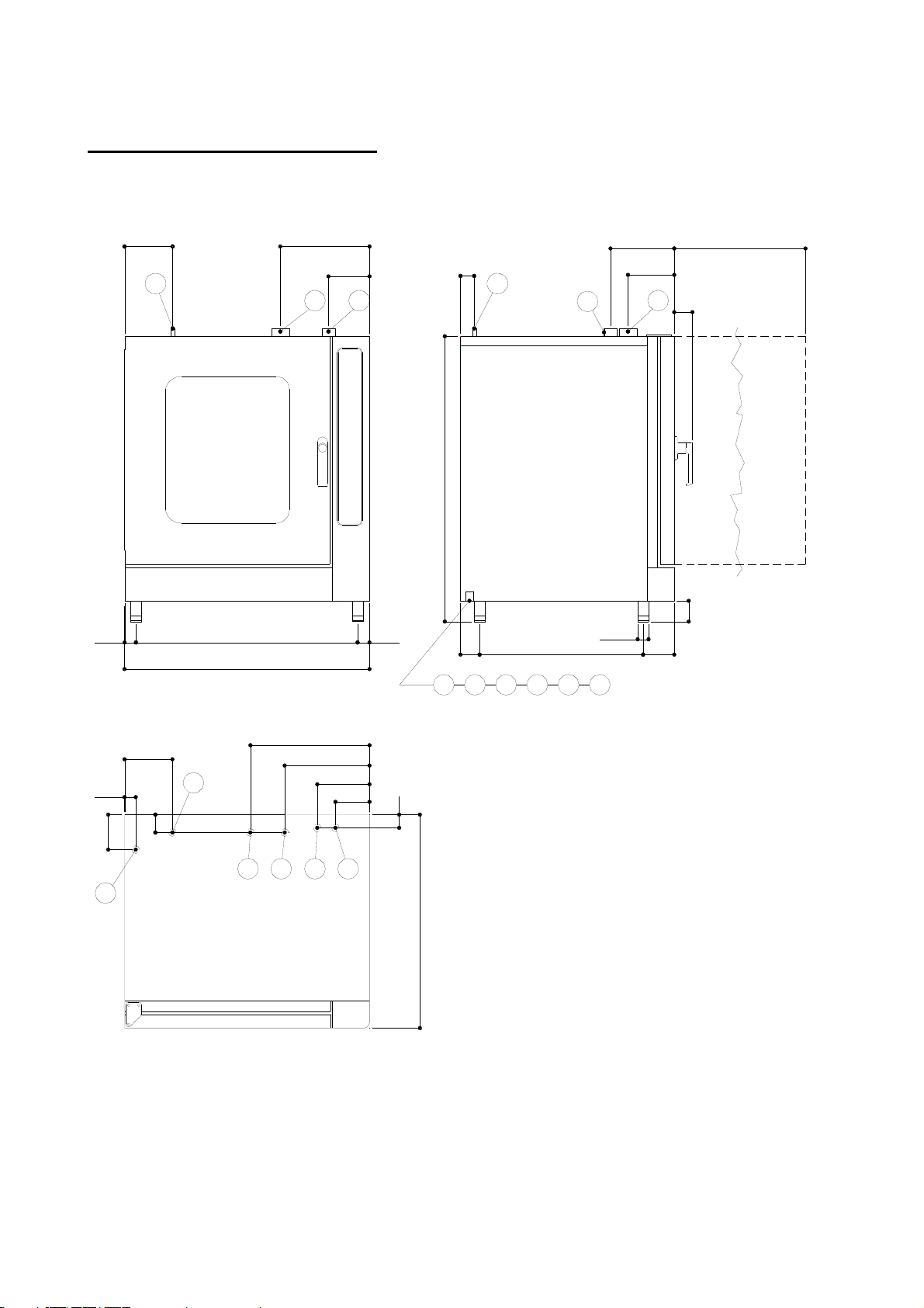
OVEN INSTALLATION DIAGRAM: - FIG. 1
LH
CH
458
326
120
69
46852
44
184
B
178
G
245
343
158
G
51
942
760
74
70
80
B
1100
DCA
F
131
F
823
629 Ø42
A
L
D
43
135
201
185
P53 P
KEY
A. Power cable inlet
B. Cooking fumes exhaust pipe
C. Water inlet ¾”G
D. Water release Ø25mm
G. Rapid steam exhaust
H. Water inlet (cleaning –
optional)
L. Steam reduction water inlet
(optional)
P. Pipe for boiler cleaning (only
for MX version)

3
INSTRUCTIONS FOR THE INSTALLER
1. POSITIONING THE OVEN
Position the equipment on a horizontal surface, well-balanced. The distance of the back and
side panels of the oven from the wall must be of at least 50 cm.
2. INSTALLATION
Remove the plastic adhesive film before starting up the equipment. The glue residues must
be carefully removed. Avoid using abrasive substances.
3. ELECTRICAL CONNECTION
This oven is manufactured to operate at the voltage indicated on the relevant label. Remove
the right panel of the oven by removing the fastening screws to access the connection
terminal board The flexible cable for connection to the mains must not have characteristics
lower than the ones with rubber insulation model H07RN – F and the section must be the one
indicated in the TECHNICAL FEATURES.
Connection to the electric line must be made by inserting an automatic switch with adequate
capacity with an opening distance between the contacts of at least 3 mm Furthermore, during
operation, power supply must not be very different from the value of the nominal voltage ±
10%.
The equipment must be connected to a ground outlet. Inside the oven, in the connection
terminal board, there is a terminal with the following symbol . Connect the ground wire to
this.
The equipment must be inserted in an equipotential system, whose effectiveness must be
properly verified according to what is indicated in the regulations in force. Connection must
be made using a screw with this symbol ( EQUIPOTENTIAL) on the rear of the equipment.
The manufacturer cannot be held responsible if this accident-prevention regulation is not
observed.
4. WATER CONNECTION – Fig. 1
Use a ¾” G pipe on the solenoid in the back lower part of the oven to connect the oven to the
water line. We suggest using joints with gaskets and flexible pipes for high pressures. Verify
that at the end of the operations there are no leaks. Use only material (pipes, joints, etc.) that
complies with the regulations in force and that in any case do not leave rust build-up.
IMPORTANT: A scale inhibitor must always be installed upstream of the equipment. The
hardness of water must be lower than 3° French.
If an efficient scale inhibitor is not installed there will be scale build-up on the equipment and
this could affect its proper operation.
5. CONNECTION TO WATER DRAIN
Connect system to water drain pipe Ø25mm. (D fig. 1) on the back part of the oven’s frame.
Verify that the connected drain pipe has no bents that exceed the height of the joint itself.
Use only materials (pipes, joints, etc.) compliant with the regulations in force and that in any
case do not leave rust build-up.

4
6. STARTING -UP THE OVEN (Fig. 4)
1. Press key 1 (main switch). Wait approx. 10 seconds.
2. Press key 11.
3. Press key 7. Set the desired temperature by rotating knob the 5.
4. Press key 6. Set the cooking time by rotating the knob 5.
5. Press key 2 (Start/Stop).
1. 7. CONTROLING THE FUNCTIONS
Switch on oven in accordance with procedure 6.
Control flame ignition and the blowout when the desired temperature is reached.
5
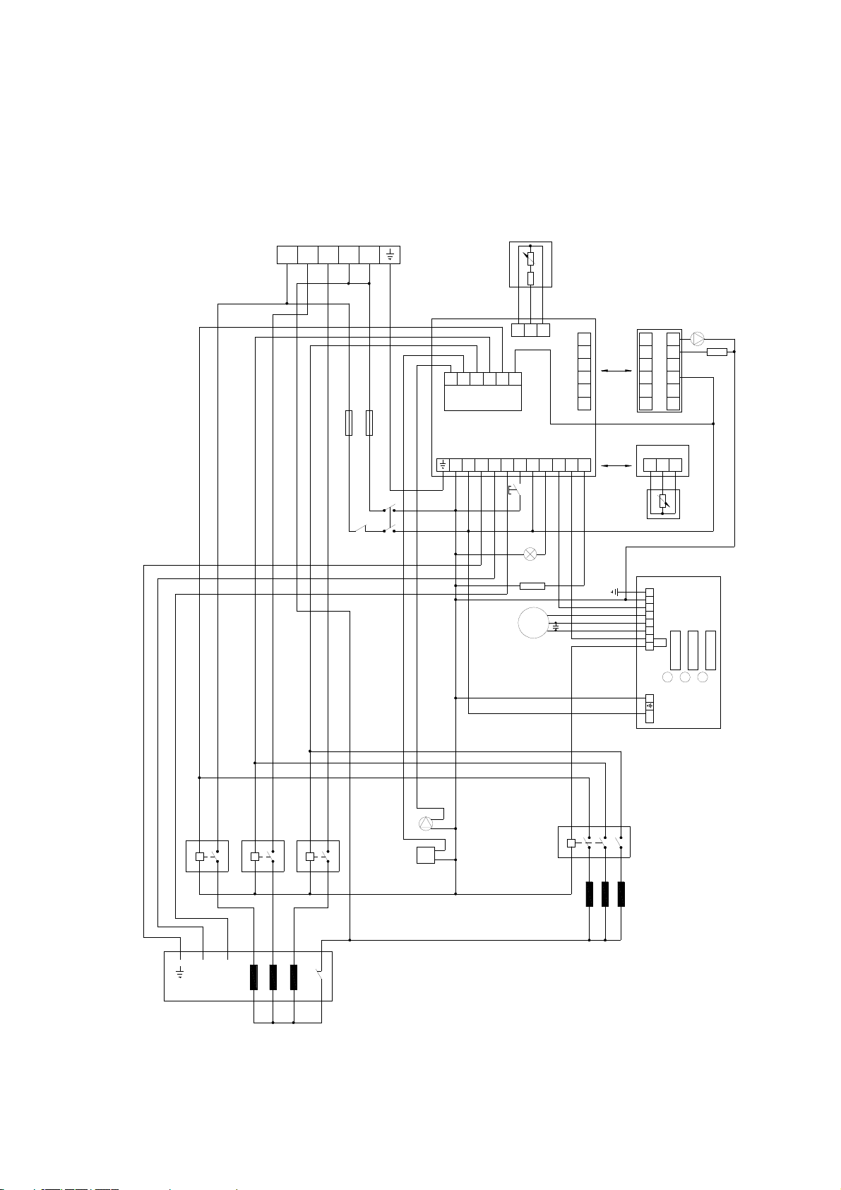
Fig. 2 WIRING DIAGRAM
P
L1
R1
R2
LP
RP L2
45678 2200123
L
11
10986534 712 292827
G
H
FLAT
C D M
N
Q~
M8µƒ
V
U
H
36
37
38
39
40
4130
31
32
33
34
3512
13
14
15
16
17
E
F
1ohm
181920
BIANCO
ROSSO
ROSSO
B
A
4
415 V ~3N
321
MIN MAX K
WWW
Z
Y
26 25 24 23 22 21 J
R
S
R
3215
L1L2L3NN
TF

6
WIRING DIAGRAM KEY
A. Terminals
B. Fuses
C. Safety thermostat
D. Main switch
E. USL board
F. Pt100 probe
G. Expansion module
H. Washing expansion board
K. Boiler 3 Kw (min=minimum level probe – max=maximum level probe – TF=thermofuse
L. Door microswitch
M. Inside light (x2)
N. Humidifier water inlet solenoid.
Q. Motor-fan
R. Armored resistor
S. Resistor contactor
U. Detergent peristaltic pump
V. Washing water inlet solenoid
W. Boiler contactor
J. Expansion module MX
Y. Drain pump
Z. Boiler solenoid

7
TECHNICAL SPECIFICATIONS OVEN 10 EMX - usl
Power KW. : 21,8
Voltage : 400 V 3N ~
Connection cable (H07RN – F) :5x6mm² for power 380V
Water inlet pressure : 2 bar min.
: 6 bar max.
Water connection : ¾” G
Connection to water drain : pipe Ø25mm.
TABLE 1
8
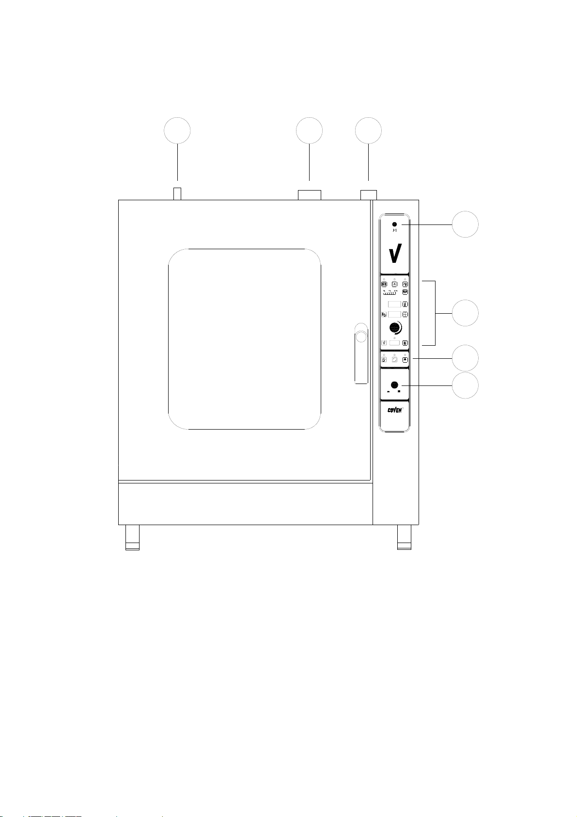
INSTRUCTIONS FOR USER
c
c
c
3
2
1
45
6
7
c
R
OFFON
POWER
Rwash
START
STOP
SUPER
Fig. 3
1. Mains switch
2. Electronic board
3. Rapid steam exhaust control button
4. Rapid steam exhaust
5. Cooking steam exhaust
6. Controls: core temperature probe, Food thawing, Washing (optional)
7. Descaling solution inlet.
Table des matières
Autres manuels Coven Four


