CornellCookson FS-150EP Series Guide de dépannage

INSTALLATION INSTRUCTIONS
AND
OPERATION MANUAL
FS-150EP Series (v2)
(230V-1Ph-50Hz)
(230V-3Ph-50Hz)
Rolling Fire Door Operators
UL325-2010 Compliant
Restricted Duty Operators
SMART Control

1
FS-150EP Series
230V, 50Hz
REVISION # 0000
DATE: 02/18/2021
IMPORTANT INSTALLATION INSTRUCTIONS
WARNING –To reduce the risk of death or serious injury to
persons:
1. READ AND FOLLOW ALL INSTALLATION INSTRUCTIONS.
WARNING! – Components under extreme spring tension can cause death or serious injury.
2. Install only on a properly operating and balanced door. A door that is operating improperly could
cause death or serious injury. Trained door systems technicians make all necessary adjustments
and repairs to the door before installing the operator.
Note: Fire door spring tension must be adjusted per the manufacturer’s installation instructions to
allow for automatic closing during a drop test, fusible link/alarm activation and/or power
failure (Power failure condition only applies to operators capable of fail-safe closing).
3. Remove all pull ropes.
4. Unless the door operator includes an internal lock sensing system, or external electrical interlocks
are installed, remove or make all door locks inoperative, or secure locks in the unlocked position to
prevent operation with the locks engaged.
5. Install the door operator at least 8 feet or more above the floor if the operator has exposed moving
parts. If the operator must be mounted less 8 ft (2.44 m) above the floor, then exposed moving
parts must be protected by covers or guarding. Contact the manufacturer.
6. Do not connect the door operator to the source of power until instructed to do so.
7. Locate the control station (open-close-stop push button, key station, or the like): (a) within sight of
the door, (b) at a minimum height of 5 feet above floors, landings, steps, or any other adjacent
walking surface and (c) away from all moving parts of the door.
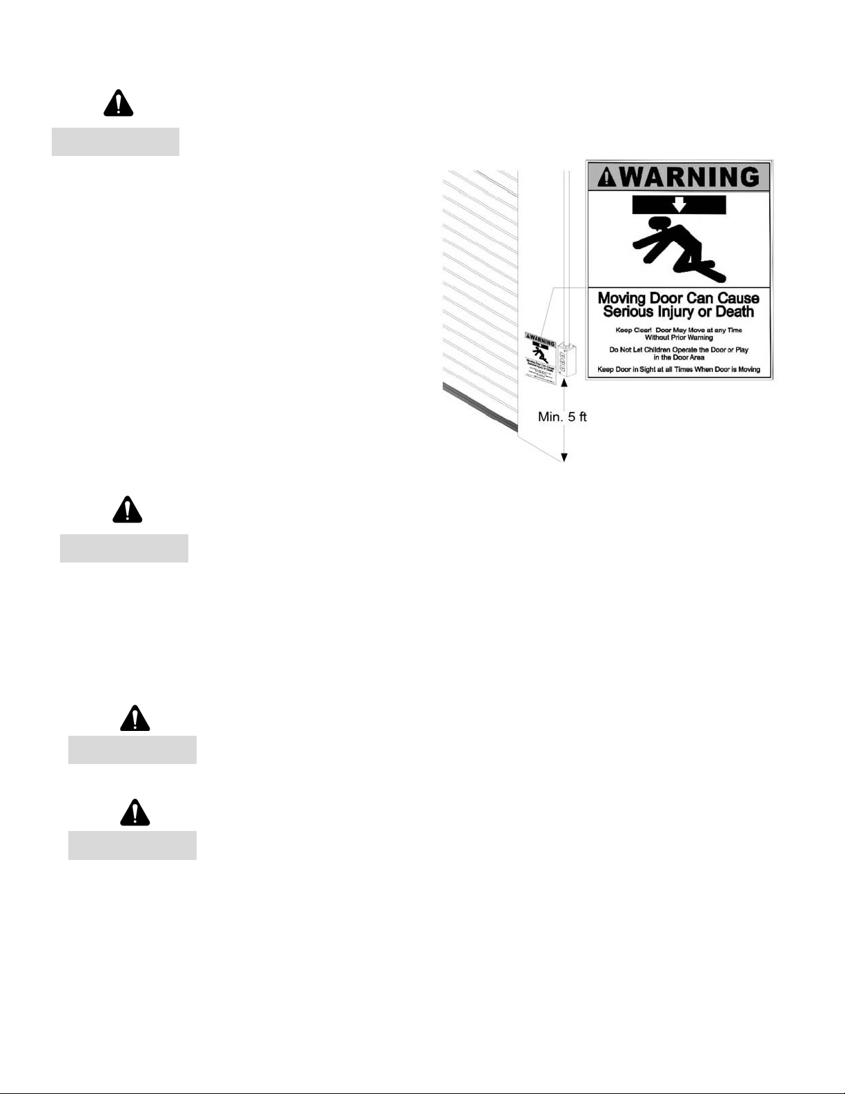
8. Install the Entrapment Warning Placard next to the control station in a prominent location.
9. Make sure the available power supply to be connected to the operator is of the same voltage,
frequency, phase and wattage as indicated on the nameplate of the operator.
10. Read and understand the wiring diagram of the operator and the control station and any other
equipment to be connected to the operator.
11. Always disconnect power whenever installing or servicing the door operator or door.
12. All wiring must be permanent and comply with National Electrical Code (NEC) and local code
requirements.
13. Any change in mounting position may result in a change of operator rotation and consequently in a
change of control functions. Consult factory for any changes.
14. For products having a manual release, instruct the end user on the operation of the manual
release.

2
FS-150EP Series
230V, 50Hz
REVISION # 0000
DATE: 02/18/2021
SPECIFICATIONS
MOTOR
Type: Restricted cycle duty (30 cycles per hour)
Horsepower: 1-1/2 hp
Speed: 1400 RPM
Voltage: 230 – 1 phase, 50Hz
208/230 – 3 phase, 50Hz
230 volt 3 phase motor is suitable for use with 208 volts
(
see Wiring Diagrams and Appendix
5
for wiring change instructions
)
Current: See motor nameplate
ELECTRICAL
Transformer: 24VAC
Wiring Type: Momentary pressure open, stop, constant pressure close
(provided standard), with provision for momentary pressure close*
Limit Adjustment: Linear driven, fully adjustable screw type cams.
MECHANICAL
Drive Reduction: 82:1
Output Shaft Speed: 17 RPM
Door Speed: 6 - 8” per sec. average (typical)
Brake: Solenoid actuated brake
ENTRAPMENT PROTECTION
Sensing Edge*: (Optional) Sensing device attached to the bottom edge of the door.
Non-Contact Device*: (Optional) Photo eye device.
* Per the requirements of UL Standard 325, the door operator is setup for constant
pressure to close the door. As an alternative, the door may be provided with a monitored
entrapment protection device that will reverse the door upon contact with or detection of
an obstruction during closing. Adding an entrapment device would enable momentary
close operation.
Notes:
1. Non-contact device (photo eye) can be used on doors up to 45 ft. wide (or maximum rated range of
device if less than 45 ft.). Use a sensing edge to provide entrapment protection on doors over 45 ft.
wide.
2. Sensing edge can be used on all doors.
3
FS-150EP Series
230V, 50Hz
REVISION # 0000
DATE: 02/18/2021
TYPES AND SIZES OF DOORS
Consult factory for details.
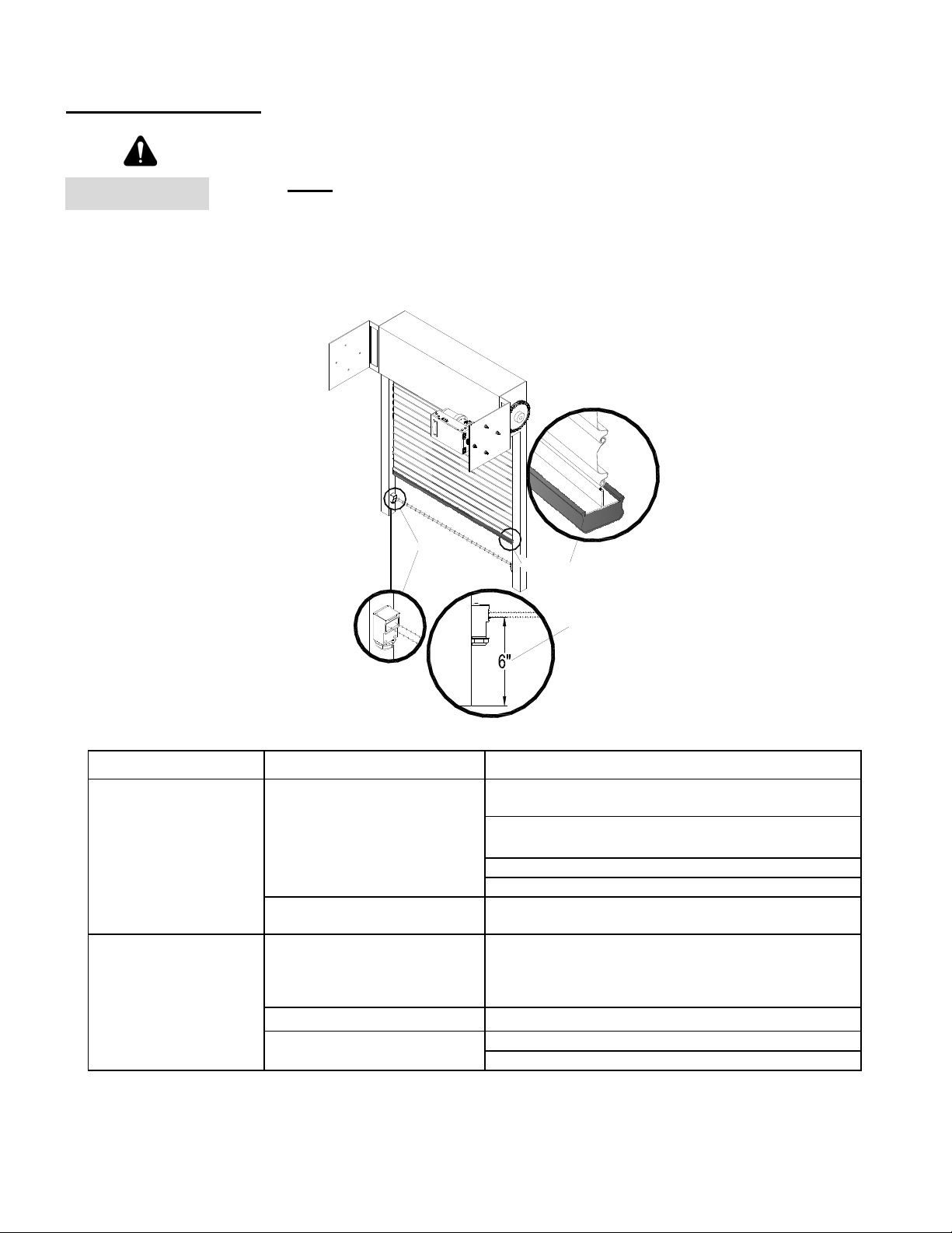
INSTALLATION INSTRUCTIONS
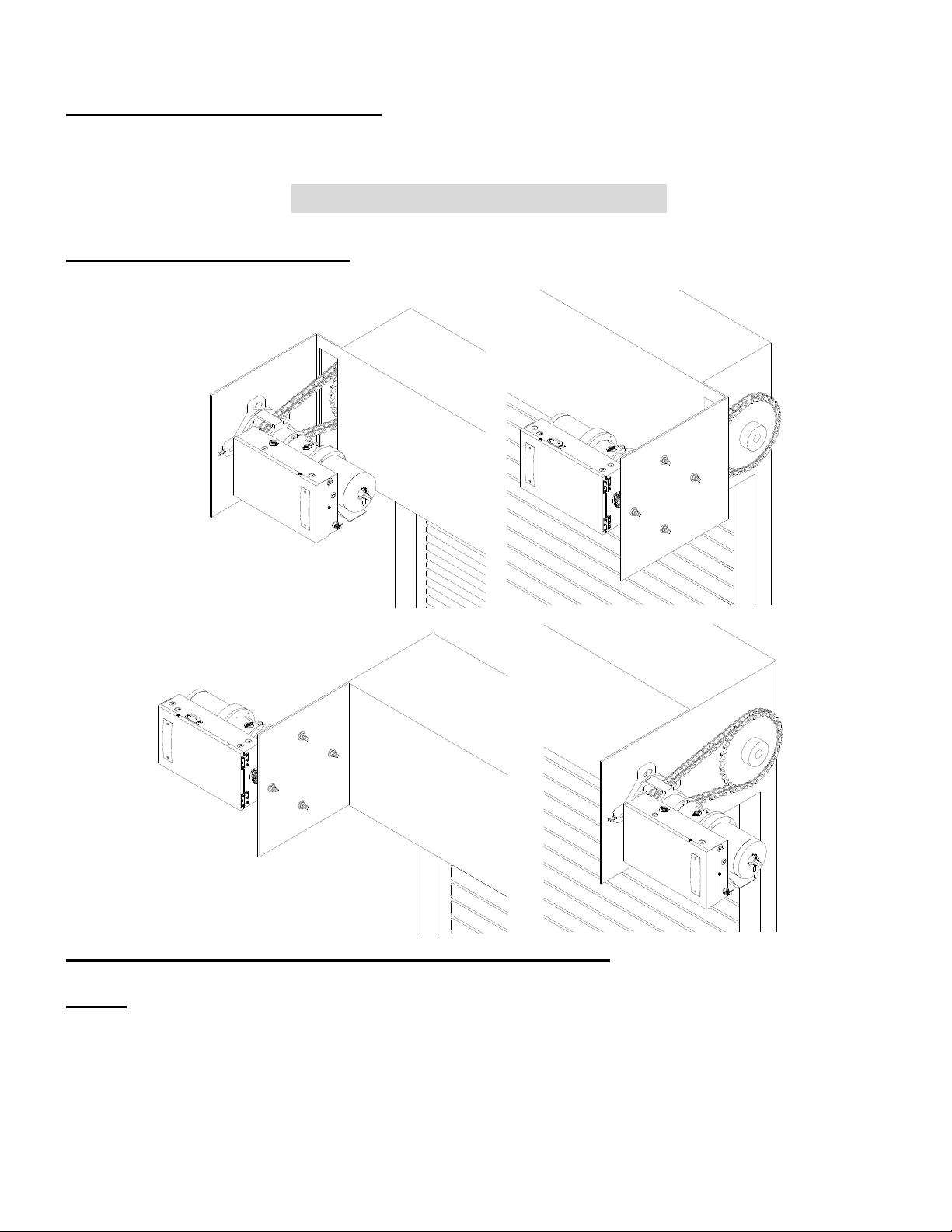
INSTALLATION POSITIONS
LA RA
RS
LS
Consult factory for changes in installation positions.
NOTE: Any change in mounting position may result in a change of operator rotation and
consequently in a change of control functions. Consult factory for any changes. (LS and RA
mounting positions are LH operators, RS and LA positions are RH operators)
4
FS-150EP Series
230V, 50Hz
REVISION # 0000
DATE: 02/18/2021
OPERATOR MOUNTING
1. Before the operator is installed, verify that the door is properly operating and balanced.
2. Make sure the layout of the mounting holes on the bracket are correct.
3. Mount the operator base to the mounting plate.
4. When the operator assembly is attached to the door bracket, be sure the door driven sprocket is
properly aligned with the operator drive sprocket before securing the driven sprocket to the shaft.
5. The shelf or bracket must provide adequate support for the operator. Prevent play between the
operator and the door shaft. The operator must be securely attached with the drive shaft parallel to
the door shaft. It may be necessary to field brace the operator/bracket.
Incorrect
Door
Sprocket
Operator
Drive
Sprocket
Correct
5
FS-150EP Series
230V, 50Hz
REVISION # 0000
DATE: 02/18/2021
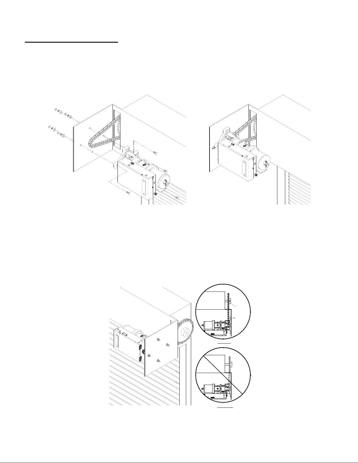
DRIVE CHAIN ADJUSTMENT
NOTE: Use correct type, size and proper length of roller chain.
1. Adjust the drive chain by tilting or move the operator so that there is about 1/4” of slack when the
chain is depressed.
Note: The set screw included in the operator may be used for adjustment. (See figure - T1, T2
location).
2. Once the drive chain has been tightened and the base leg screws have been set, and then tighten
the operator screws.
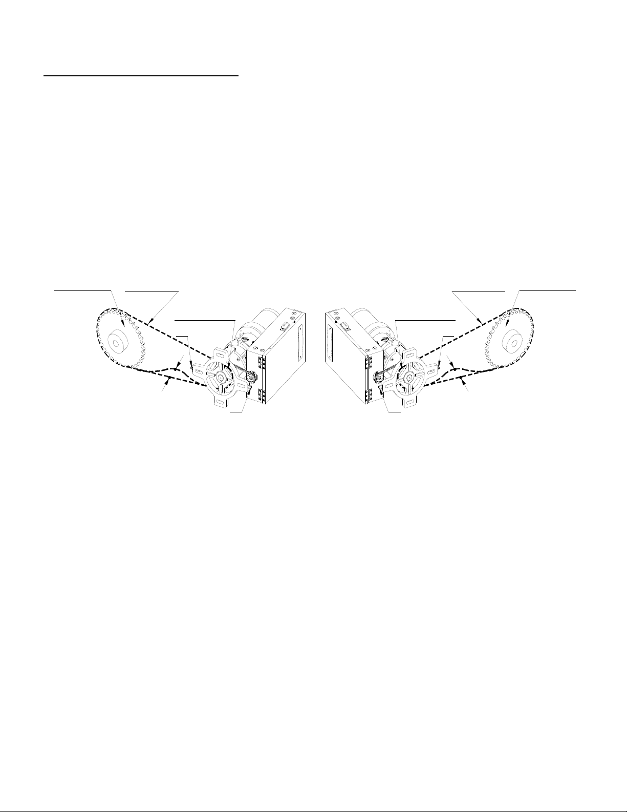
Door Sprocket Drive Chain
Drive Sprocket
T2
T1
1/4"
Door Sprocket
Drive Chain
Drive Sprocket
T2
T1
1/4"
6
FS-150EP Series
230V, 50Hz
REVISION # 0000
DATE: 02/18/2021
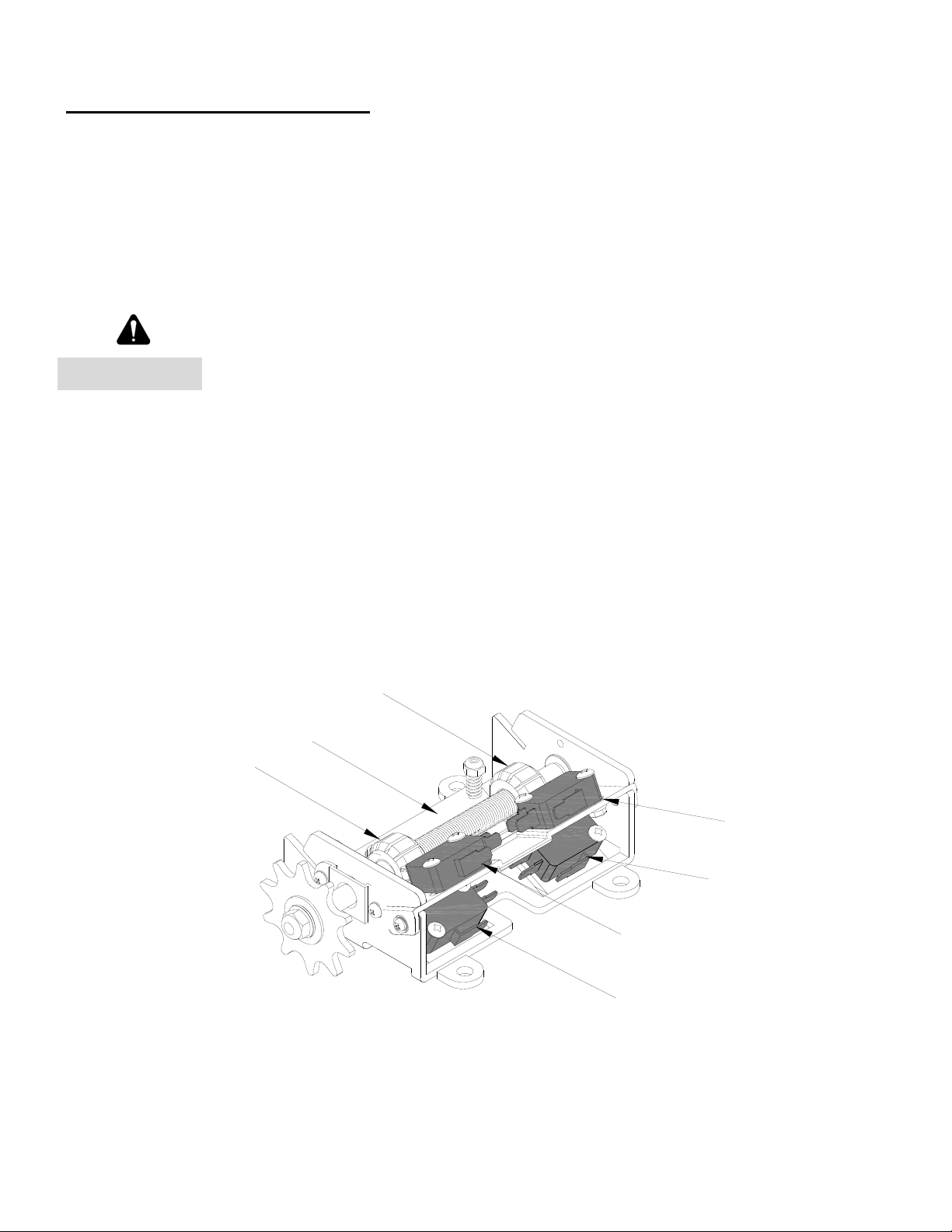
LIMIT SWITCH ADJUSTMENT
Make sure the limit cams are positioned between the limit switch actuators before proceeding
with adjustments.
1. Open / remove the control panel cover.
2. Open or close door to determine the moving direction of the limit switch cams.
3. Open or close door to the desired position.
Disconnect power before adjusting limit switch cams.
4. While pressing the spring-loaded lever (G), which holds the limit switch cams in place, adjust the
limit switch cam (E or F) until the micro switch (C or D) clicking sound is heard.
5. If the limit switch cam cannot be rotated to its desired position, release the lever and move the door
away from the desired position, then adjust the limit switch cam to its desired position. It may be
necessary to repeat this step until the exact position has been reached.
6. Repeat step 3 and 4 for the opposite direction. Adjust close limit cams so that actuator is engaged
as door fully seats at the floor.
7. Micro switch (A or B) can be adjusted to accommodate sensing edge cut-off position.
A
D
B
C
F
G
E
NOTE: “C” is usually the opening side and “D” is usually the closing side.
WARNING

7
FS-150EP Series
230V, 50Hz
REVISION # 0000
DATE: 02/18/2021
WIRING INSTRUCTIONS
Disconnect power at the fuse box before proceeding with any wiring.
1. Do not install any wiring or attempt to run this operator without checking the wiring diagram located
on the inside of the control box cover.
2. Do not turn on power until you have finished making all power and control wiring connections.
3. Do not run power and control wiring in the same conduit.
4. Any wire connected to the control panel must be protected by conduit or other means to ensure the
safety and permanency of the wiring.
5. Use copper wire inside the control panel.
6. A separate fuse line of adequate capacity is needed for the operator.
7. The operator must be properly grounded. The ground screw, painted green, is located inside the
control panel.
8. For an operator, system, or external device requiring field installed wiring between a Class 2 output
of an operator and an external device, the type of wiring shall be R/C (AVLV2/8), AWM, min. 22
AWG, rated 60°C, with VW-1/FT2.
Failure to properly ground the operator could result in electric shock and
death or serious injury.
Unless the operator includes an internal lock sensing system, or external
electrical interlocks are installed, remove or make all door locks inoperative,
or secure locks in the unlocked position. Failure to disable the locks could
result in damage to the door or operator.
WARNING
WARNING
WARNING
8
FS-150EP Series
230V, 50Hz
REVISION # 0000
DATE: 02/18/2021
CONTROL WIRING
If the door is not visible from the control station, or if any device other than
the control station is used to activate the door, an entrapment protection
device must be installed on the door. Failure to install an entrapment
protection device may result in serious injury or death to person(s) trapped
beneath the door.
1. Complete limit switch adjustments before making any sensing edge/non-contact device wiring
connections to the operator.
Sensing Edge
Photo Eye
6" max. above floor
Entrapment Device Options:
Sensing Module Device Manufacturer Model
ELR
2-wire resistive sensing
edge
Miller Edge Inc.
* End of Line resistor type
edge must have model
number with Suffix T2.
ME110*, ME111*, ME120*, ME123*, ME112*,
ME113*, ME116*, ME117*
MT21*, MU21*, MT22*, MU22*, MC22*, MU33*,
MC271*, CPT223*
MEL-TXYY, MEL-RXYY
RB-G-K10
ASO GE225, GE125, GE245, GE F45, GE F50, GE F56,
GE F65, GE F85, GE F115
IR
Monitored photo eye
FRABA Inc.
Optical Edge Sensors and Photo Eyes, Models
OPTOEDGE, OPTOEYE, OSE, OPE, OSE-P,
OSE-R, OSE-T, RAY-N
Reflective Photo E
y
e, Models Ra
y
/RT -1004, -2004
Martec Access Products Inc. 1266
Miller Edge Inc. IG2, MIRM
RB-D-K10
Note: Please refer to sensing device manufacturer for specific installation and maintenance requirements.
WARNING
WARNING
9
FS-150EP Series
230V, 50Hz
REVISION # 0000
DATE: 02/18/2021
Disconnect power at the fuse box before proceeding with any wiring.
2. Locate the control station where the user can
clearly see the operation of the door. Mount
the enclosed placard adjacent or near the
door.
Controls shall be far enough from the door, or positioned such that the
user is prevented from coming in contact with door while operating the
controls.
3. Do not run control wiring in the same conduit as power wiring.
4. Any wire connected to the control panel must be protected by conduit or other means to ensure the
safety and permanency of the wiring.
Do not use radio controls with your operator unless some type of
entrapment protection device has been installed. Failure to do so may
result in death or serious injury to person(s) trapped beneath the door.
Changing from left hand to right hand or vice versa could result in change
of control wiring. Consult factory for details.
5. After installation, be sure that the operator, controls, and sensing edge or other entrapment
protection devices have been tested and function properly.
WARNING
WARNING
WARNING
WARNING
Table des matières
Autres manuels CornellCookson Système d'ouverture de porte

CornellCookson
CornellCookson FS-500EP Series Guide de dépannage

CornellCookson
CornellCookson SGH 50043E Guide de dépannage

CornellCookson
CornellCookson SGHN4-300 E Series Guide de dépannage

CornellCookson
CornellCookson SGH 30043E Guide de dépannage

CornellCookson
CornellCookson SGH Series Manuel utilisateur

CornellCookson
CornellCookson FS-36EP Series Guide de dépannage

CornellCookson
CornellCookson SGH 50023E Guide de dépannage

CornellCookson
CornellCookson SGHN4-100 Series Guide de dépannage

CornellCookson
CornellCookson AlarmGard FST-EPBD Series Guide de dépannage

CornellCookson
CornellCookson SDCL-5045 Guide de dépannage


