5
www.cmovalves.com
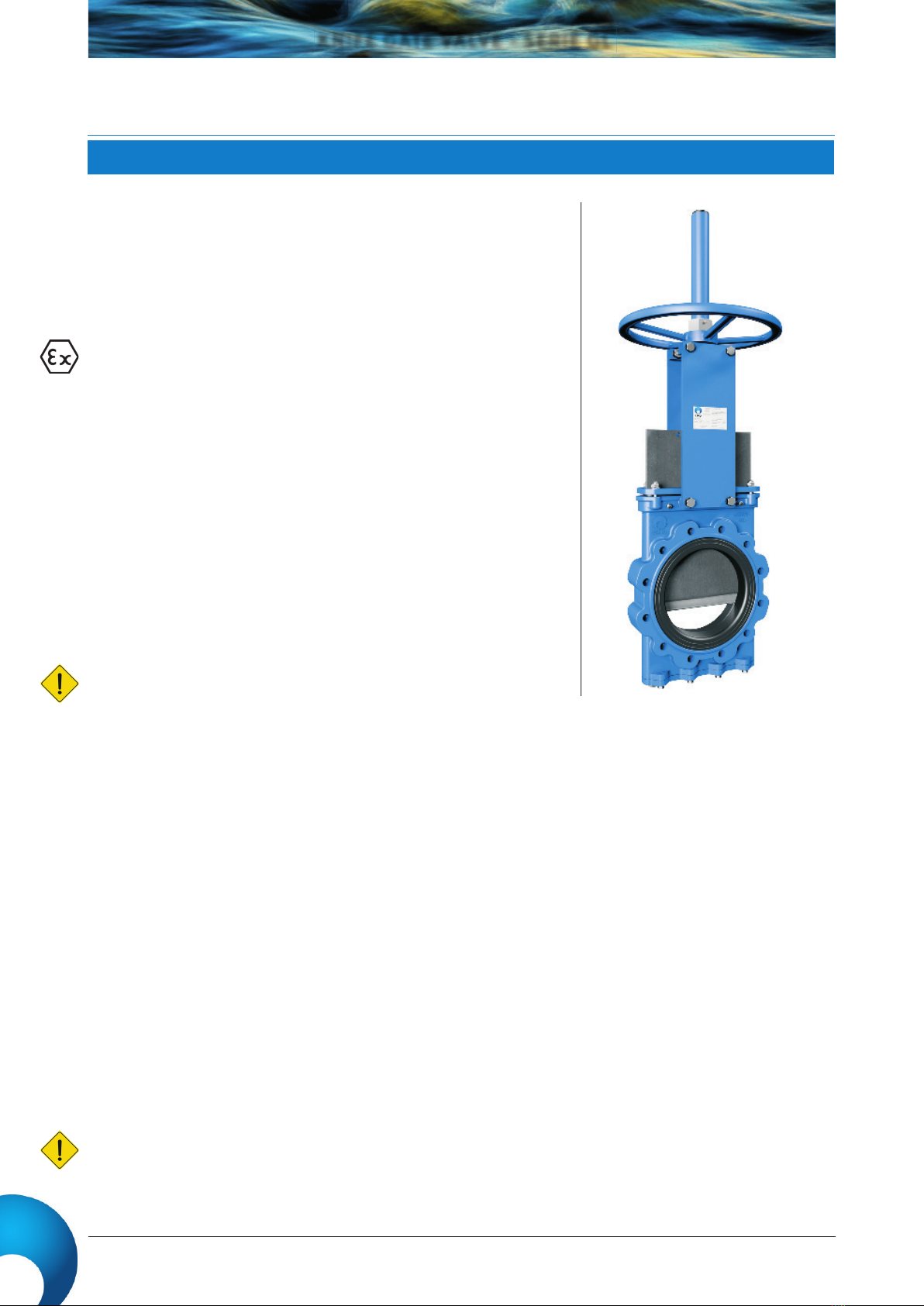
KNIFE GATE VALVE - SERIE GL
Rev.08 16-05-2019
To operate the valve: Turn the handwheel clockwise to close or anticlockwise to open.
To operate the valve pull one of the chain’s vertical drops, taking into account that locking is carried out when the chainwheel
turns clockwise.
First loosen the position locking clamp located on the yoke. Once it is unlocked raise the lever to open or lower it to close. To
complete the operation lock the lever again.
CMO pneumatic actuators are designed to be connected to a 6 kg/cm pneumatic network, although these cylinders support up
to 10 kg/cm2. The pressurised air used for the pneumatic actuator must be correctly filtered and lubricated. This type of actuator
does not require any adjustment, due to the fact that the pneumatic cylinder is designed for the exact stroke required by the
valve
CMO hydraulic actuators are designed to work at a standard pressure of 170 kg/cm2. This type of actuator does not require any
adjustment, due to the fact that the hydraulic cylinder is designed for the exact stroke required by the valve.
If the valve incorporates a motorised actuator it will be accompanied with the electric actuator supplier’s instructions.
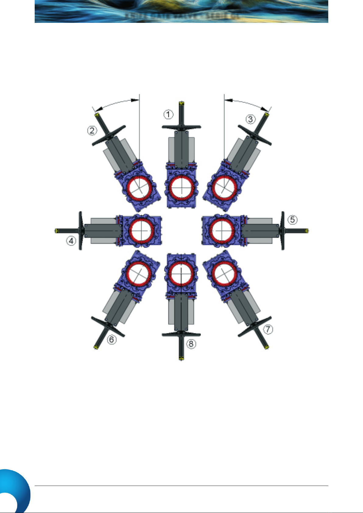
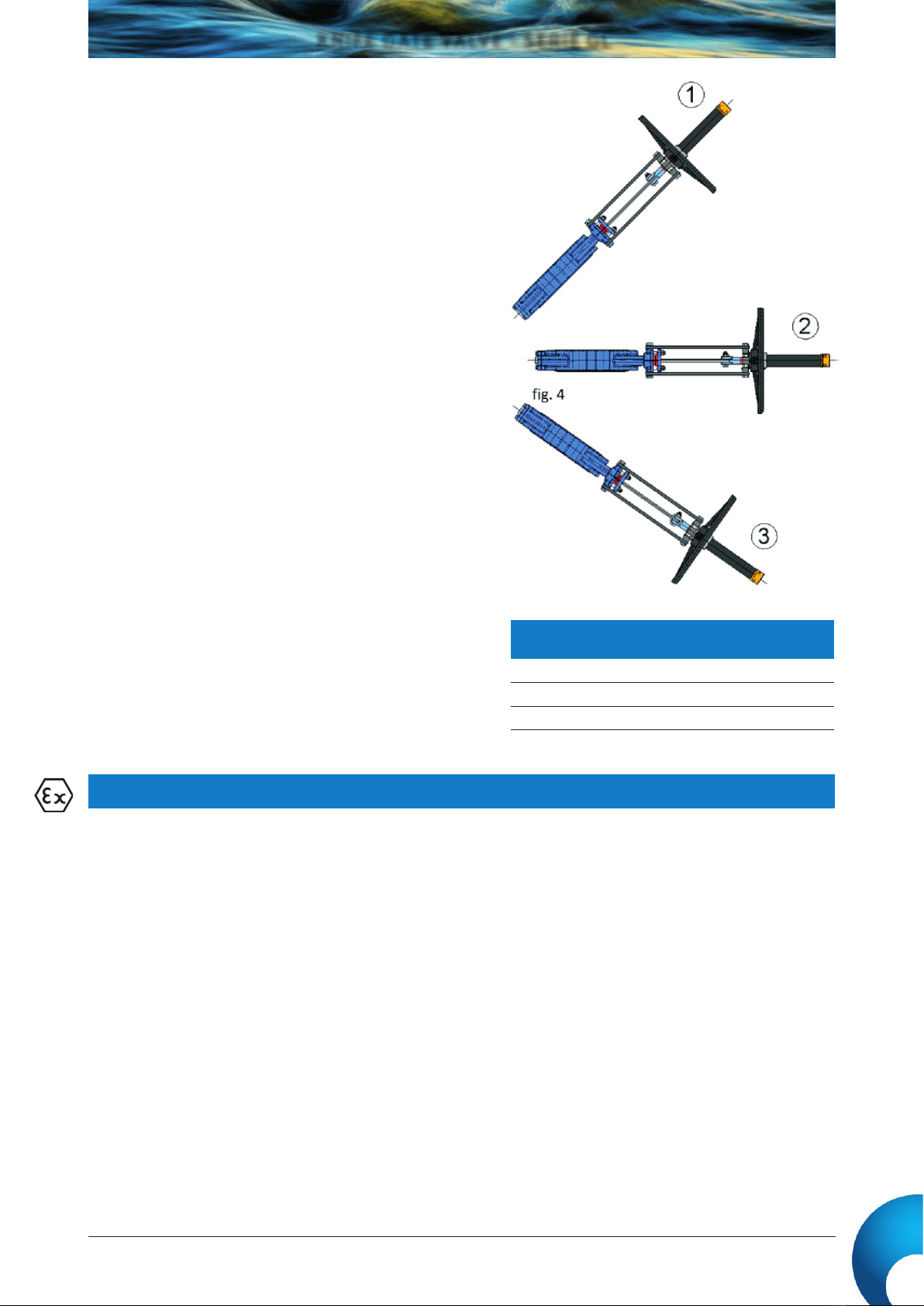
CMO valves can be assembled in all positions; however, certain
aspects must be taken into account:
Positions 1, 2 y 3: In these positions, it is recommended to make
a suitable support, because, due to the weight of the actuator,
deformations may arise and this can lead to operating problems in
the valves.
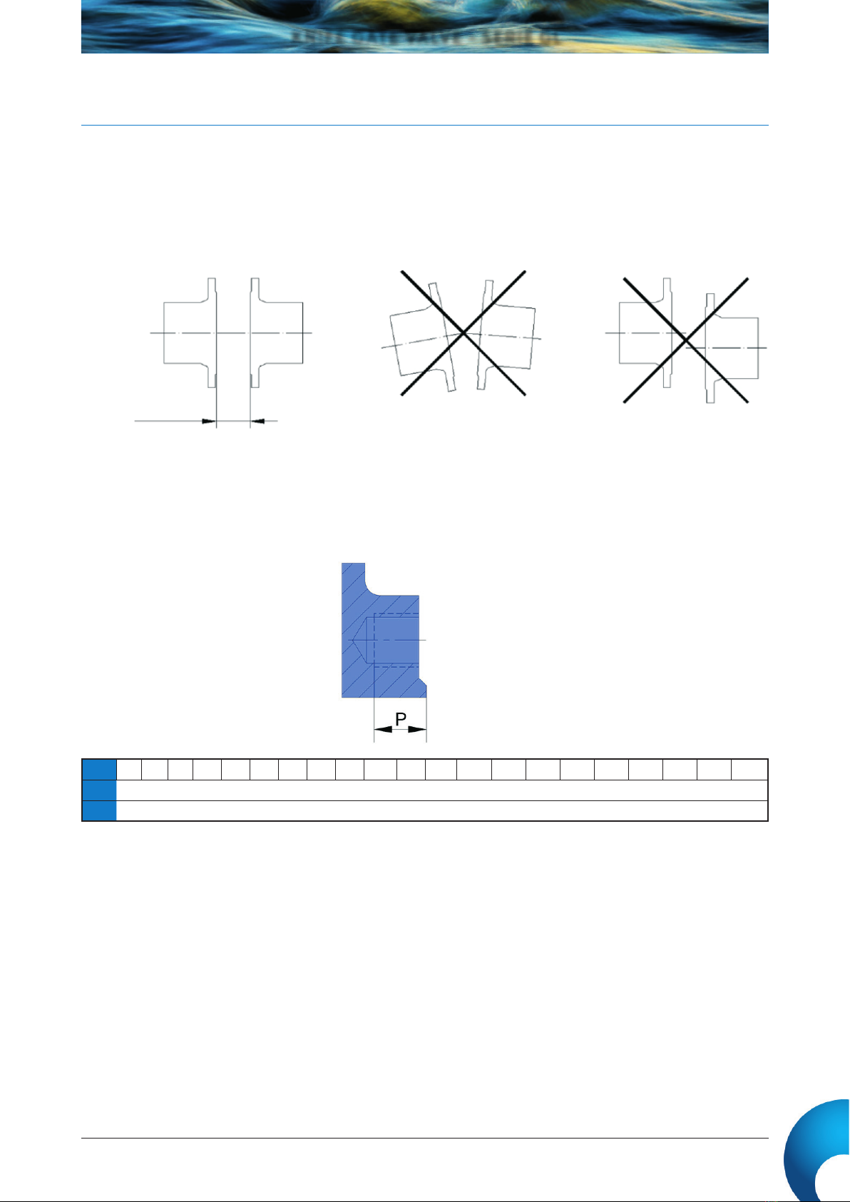
Once the valve has been installed, check that all the screws and
nuts have been correctly tightened and that the whole valve
action system has been correctly adjusted (electrical connections,
pneumatic connections, instruments…).
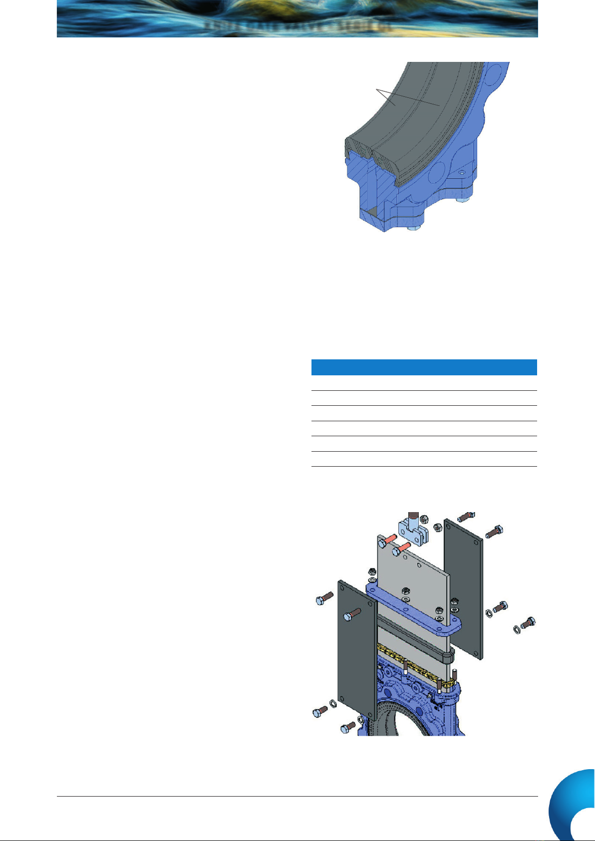
All CMO valves are tested at its facilities, however, during the
handling and transport the screws on the packing gland can come
loose and must be re-tightened. Once the valve is installed in the
pipeline and it has been pressurised, it is very important to check for
any leakages from the packing gland to the atmosphere.
In the event of a leakage, tighten the nuts on the packing gland
crosswise until the leakage stops, ensuring that there is no contact
between the packing gland and the gate.
A very high tightening torque on the packing gland’s nuts can lead
to problems, such as an increase in the valve’s torque, reduction in
the packing’s working life, or the breaking of the packing gland. The
tightening torques are indicated in Table 2
Once the valve is installed in its place, check that the flanges and
electrical and pneumatic connections are secure. If the valve has
electrical accessories or you are in an ATEX zone, earth connections
must be made before operating it.
If you are in an ATEX zone, check the continuity between the valve
and the pipeline (EN 12266-2, annex B, points B.2.2.2. and B.2.3.1.).
Check the pipeline’s earth connection and the conductivity between
the outlet and inlet pipelines
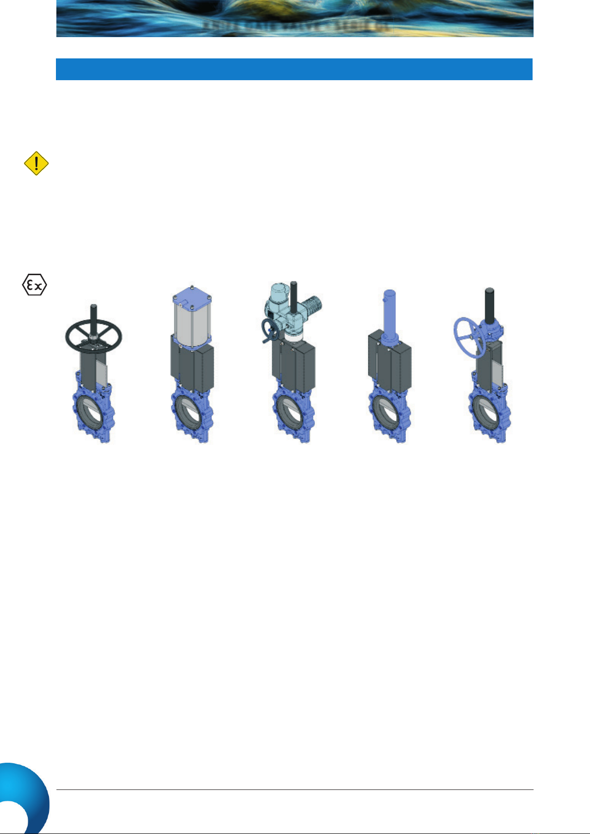
ASSEMBLY POSITIONS (Vertical/Inclined Pipe)
HANDWHEEL (Rising or Non-Rising Stem and Stem with Gear Box)
CHAINWHEEL
LEVER
PNEUMATIC (Double and Single Acting)
HIDRAULIC
MOTORISED (Rising or Non-Rising Stem)
TIGHTENING TORQUES FOR PACKING GLAND
SCREWS
ND50 a ND125 25 Nm
ND150 a ND300 30 Nm
ND350 a ND1400 55 Nm
ACTUATOR
Table. 2